4.1.2. One axis system
Single-axis controller model is a controller board in a metal case. Case dimensions are 62 x 44 x 124 mm.
Front panel of the controller contains power supply connector, USB-B data connector, status LED, power LED, left and right limit switch
LEDs, left and right movement buttons.
Rear panel contains positioner connector.
Connectors
Positioner connector
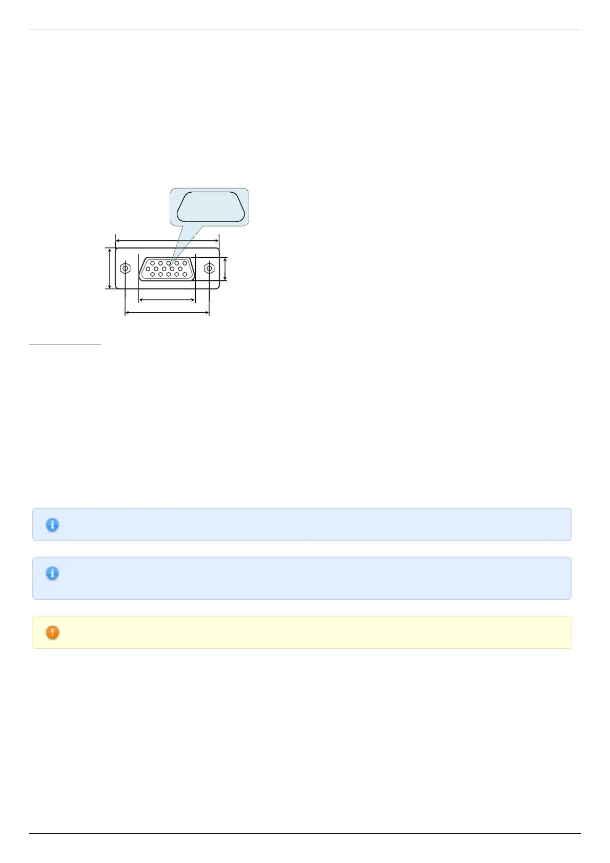
A female DSub 15-pin connector for positioner is mounted on the controller board.
Dimensions and numbers of the pins in DSub connector (front view).
Pins functionality:
1 - Not phase B of SM or - DC of the motor
2 - Phase B of SM or + DC of the motor or phase B on BLDC motor
3 - Not phase A of SM or - DC of the motor or phase C on BLDC motor
4 - Phase A of SM or + DC of the motor or phase A on BLDC motor
5 - 500mA - for 8SMC5, stabilized output for encoder power supply
6 - One-wire interface for positioner identification (for Standa hardware only)
7 - Logic ground for limit switches, encoder, etc.
8 - 2nd limit switch
9 - 1st limit switch
10 - Encoder channel A
11 - Encoder channel B
12 - Revolution sensor input
13 - Inverted Encoder channel A
14 - Inverted Encoder channel B
15 - Inverted revolution sensor input
Note. Only firmwares 4.1.0 and older support BLDC
Note. Outputs 1 & 3 and 2 & 4 must be connected together for proper DC motor function if the nominal current of the
motor is higher than 3A.
Warning. Plugging in/out the motor to the controller is not recommended while motor windings are under voltage.
Power supply connector. 1 and 2 axes system