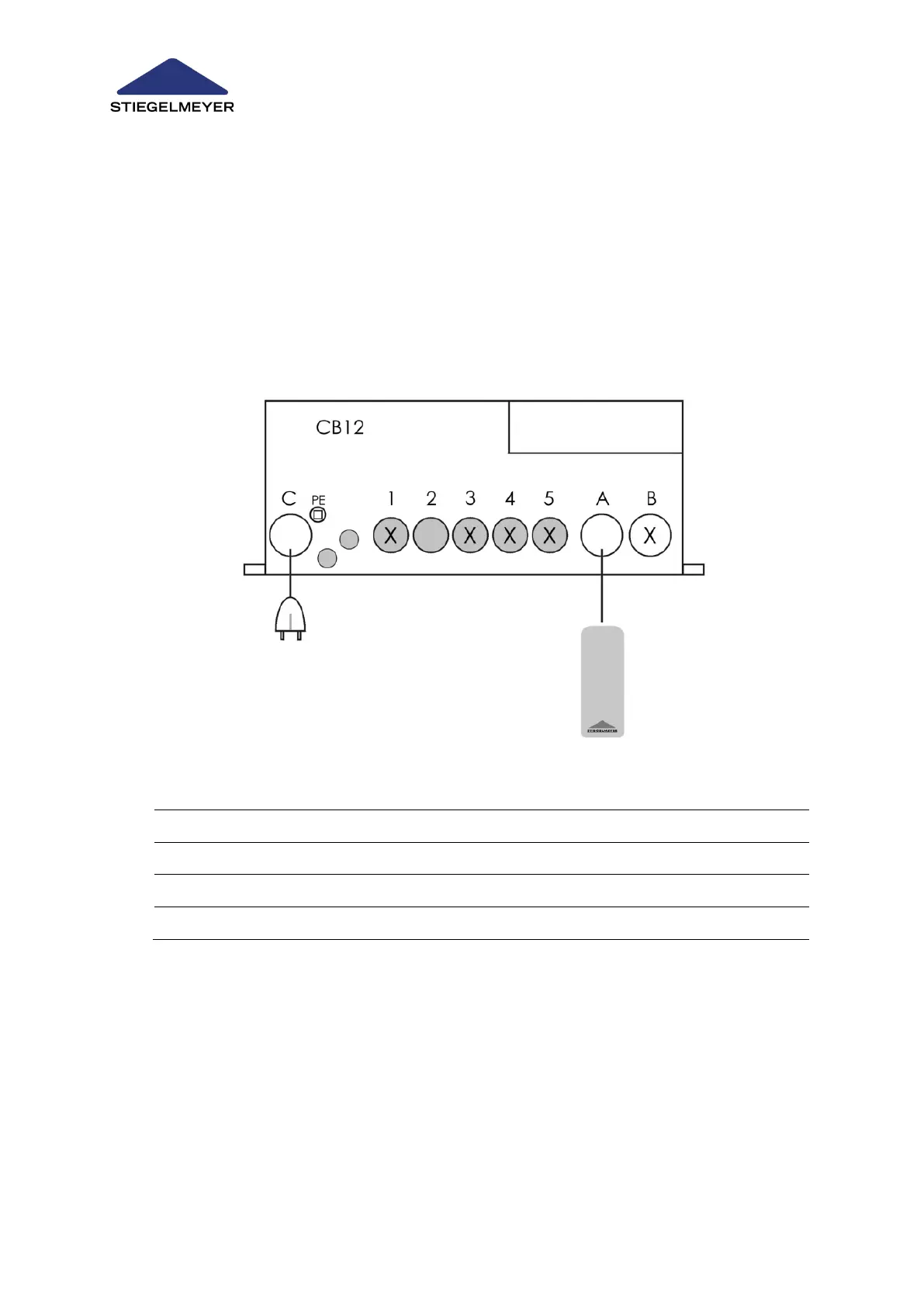
14.2 Assignment of Control Unit Terminals
Depending on the number of actuators EM1, EM2, EM3 and additional options such as handset
and locking box, the sockets on the control unit may be occupied to a greater or lesser extent. The
wiring diagram below shows all possible variants for an actuator system.
14.2.1 Variant EM1 Plug Assignment
One actuator (EM1) for backrest adjustment.