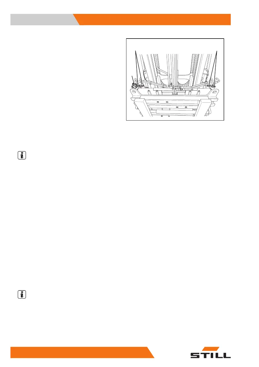
Attachment example for an attachment for ad-
justment of the fork arms
1 Auxiliary hydraulics1
2 Auxiliary hydraulics2
3 Electrical connection for switch valve1
(two switch valves are possible)
If an attachment is connected to the auxiliary
hydraulics1(1) and this attachment requires
another function, this is referred to as the
function of the auxiliary hydraulics3.
There is an electrical connection(3) for the
switch valve that is required for this purpose.
The same applies to the auxiliary hydraulics4,
which is fed from the auxiliary hydraulics2(2)
and is implemented by an additional connec-
tion for a switch valve that is not shown here.
NOTE
If one switch valve is used, the auxiliary hy-
draulic functions1 & 3 and 2 & 4 that are sup-
plied by this switch valve cannot be operated
simultaneously. The switch valve supplies ei-
ther auxiliary hydraulics1 & 3 or 2 & 4.
Adjusting the hydraulic speed for
attachments
If different attachments are mounted, the fleet
manager can adjust the hydraulic speed for
attachments and thus the flow rate of hydraul-
ic oil. Obtain the necessary values from the
operating instructions for the attachment. The
authorised service centre will help to make the
correct adjustments.
The "Information on the auxiliary hydraulics"
differs depending on the truck. Take this into
consideration when selecting the attachment.
NOTE
The adjustment procedure requires access
authorisation for the fleet manager. Access
to the settings menu is only available if the
truck is at a standstill and the parking brake
is applied. If the parking brake is released pre-
maturely, the settings menu will close.
– Apply the parking brake.
1
3
2
Operation
4
Attachments
306 57378011527EN-12/2023 - 07