Publication no. 101557
Rev 14.1.1-2
Copyright 2006-2012 – STM Group, Inc.
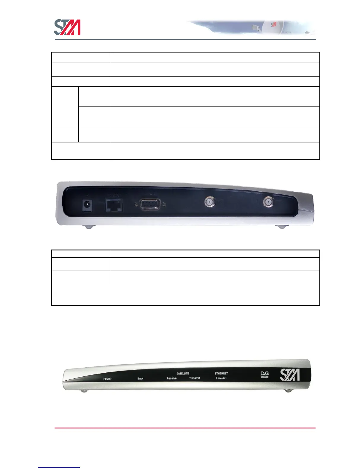
Yellow: lights steadily when connected to the power supply and unit is powered. Flashes
when loading software.
Red: lights steadily when an error event occurs and during reboot.
White: flashes when the receiver is searching for the carrier.
Lights steadily when receiver is on and functioning properly.
Flashes when IP packets are received from the Satellite Interface (the Hub).
White: flashes rapidly when a continuous wave (CW) is transmitted.
Lights steadily when the VSAT is logged on to the DVB-RCS Hub.
Flashes when IP packets are transmitted to the Satellite Interface (the Hub).
White: lights steadily when Ethernet connectivity is OK.
Flashes slowly when Ethernet packets are transferred via the Ethernet interface.
Table 1: SatLink 2000 Front Panel LEDs
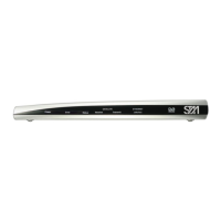
Figure 4 : SatLink 2000 Rear Panel
Connector for cable to the 24 V DC power transformer (external power supply provided
with STM SatLink 2000 VSAT)
RJ45 connector for IP traffic to connect to a PC, Ethernet switch, IP router etc. 10BASE-T
or 100BASE-T modes is detected automatically.
Nine pin connector for connecting CLI interface to a computer‘s DB-9 serial interface.
Coaxial 75 F-type jack for the cable to the LNB.
Coaxial 75 F-type jack for the cable to the BUC.
Table 2: SatLink 2000 Rear Panel Description
3.2.2 SatLink 1000 Front and Rear Panel
Figure 5: SatLink 1000 Front Panel