FFiigguurree 1100 –– IInnssttaallll ttrraannssffeerr aasssseemmbbllyy
18.Installer 1 (foot end) lifts the transfer assembly and slides the transfer lock triggers (L) (Figure 12) toward the foot end of
the transfer to release the transfer locks. Installer 2 (head end) slides and centers the open end of the transfer assembly
over the rollers in the anchor assembly.
• When you install the transfer assembly, slowly slide the transfer assembly. Do not break the cot inductive charge
housing (K) (Figure 10).
• Keep the transfer lock triggers pulled toward the foot end until the transfer is seated on the anchor (
Figure 12).
• You may notice slight resistance when you roll over the second set of rollers; push past the resistance to the position
shown in
Figure 12.
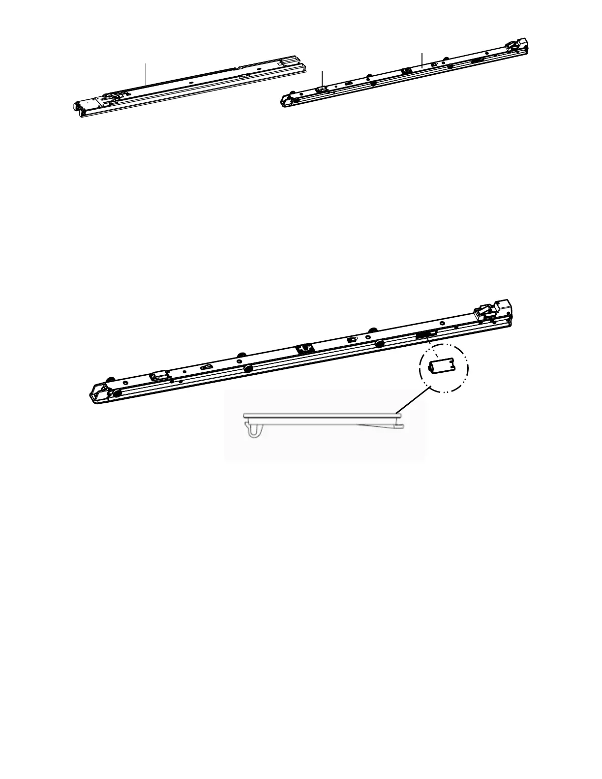
19.Position the anchor inductive primary cover (639001010101) over the opening so the U-hook faces the foot end of the
anchor (
Figure 11).
FFiigguurree 1111 –– AAnncchhoorr iinndduuccttiivvee pprriimmaarryy ccoovveerr
NNoottee -- Do not let the connectors (installed on step 16) push against the anchor inductive primary cover.
20.Using a flat blade screwdriver, press the U-hook into the anchor until you hear it click into place (Figure 11).
21.Using a 5/32'' hex wrench, install the supplied socket head cap screw (0004-658-000) (O) to secure the supplied trolley
magnet activator (6390-001-106) (P) (
Figure 12).
22.Using a T25 Torx driver, install four supplied button head cap screws (0004-665-000) (M) to attach the supplied foot end
transfer wear pad (6390-001-225) (N) to the transfer assembly (
Figure 12).
23.Slide the transfer lock triggers (closest to the foot end) (L) (
Figure 12) toward the foot end of the transfer assembly to
unlock.
6390-709-001 Rev AB.1 19 EN
 Loading...