5 Hardware
User Manual 30/374
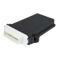
5.3 Pin Assignment
Connector view:
For mating connector see Connector (see "Connector" on page 35)
Pin numbers of the TC1:
Digital Output (int. 10kOhm pull down, max. 400[mA] @ 12V)
+UB power supply (9-32VDC)
KL15 / D+ (switched power / ignition switch)
Digital Input (int. 10kOhm pull down)
RS232 RxD (connect to PC - SUB-D Pin3)
RS232 TxD (connect to PC - SUB-D Pin2)
CAN1 low (termination required)
CAN1 high (termination required)
CAN2 low (termination required)
CAN2 high (termination required)
Ethernet Rx- (equals a PCs RJ45 - Pin 6)