© 2022 STYPE; ALL RIGHTS RESERVED.
37
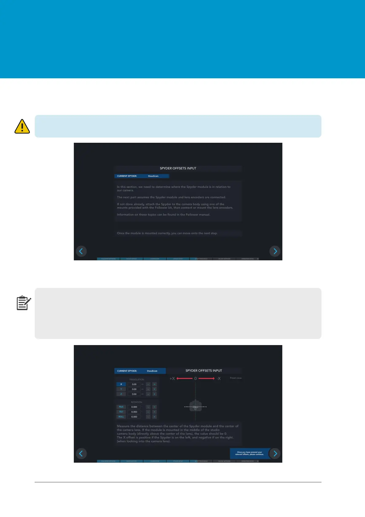
Figure 13.6 Spyder offsets input
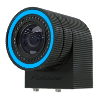
Step 5
Step 6
Translational offsets are set by measuring the relative distances from the Spyder module to the camera
image sensor and rotational offsets measure the angle of the module. As you adjust each offset you
can see a visual representation of your changes on the right. For example, if the module is mounted
center to the studio camera body (as shown in the Figure 13.6), the X value should be 0. The X offset
is positive if the Spyder is on the left, and negative if on the right (when looking into the camera lens).
Figure 13.5 Insuring Spyder and lens encoders mounting
Make sure Spyder is mounted to the camera body and lens encoders are mounted or connected.