Installation, Operation, and Maintenance Manual
12 SUMMIT PUMP MODEL 2196 / 2196-LF / 2196-R / 2796
APPENDIX A - IMPELLER CLEARANCE SETTING
A gradual loss in head and/or capacity can occur. You may restore performance by
adjusting the impeller clearance, which is the measurement between the impeller
vanes and the surface of the casing.
Table 6
Temperature Impeller Clearance
200° F (93°C)
.015” (.38 mm)
250° F (121°C)
.017” (.43 mm)
300° F (144°C)
.019” (.48 mm)
350° F (177°C)
.021” (.53 mm)
400° F (204°C)
.023” (.58 mm)
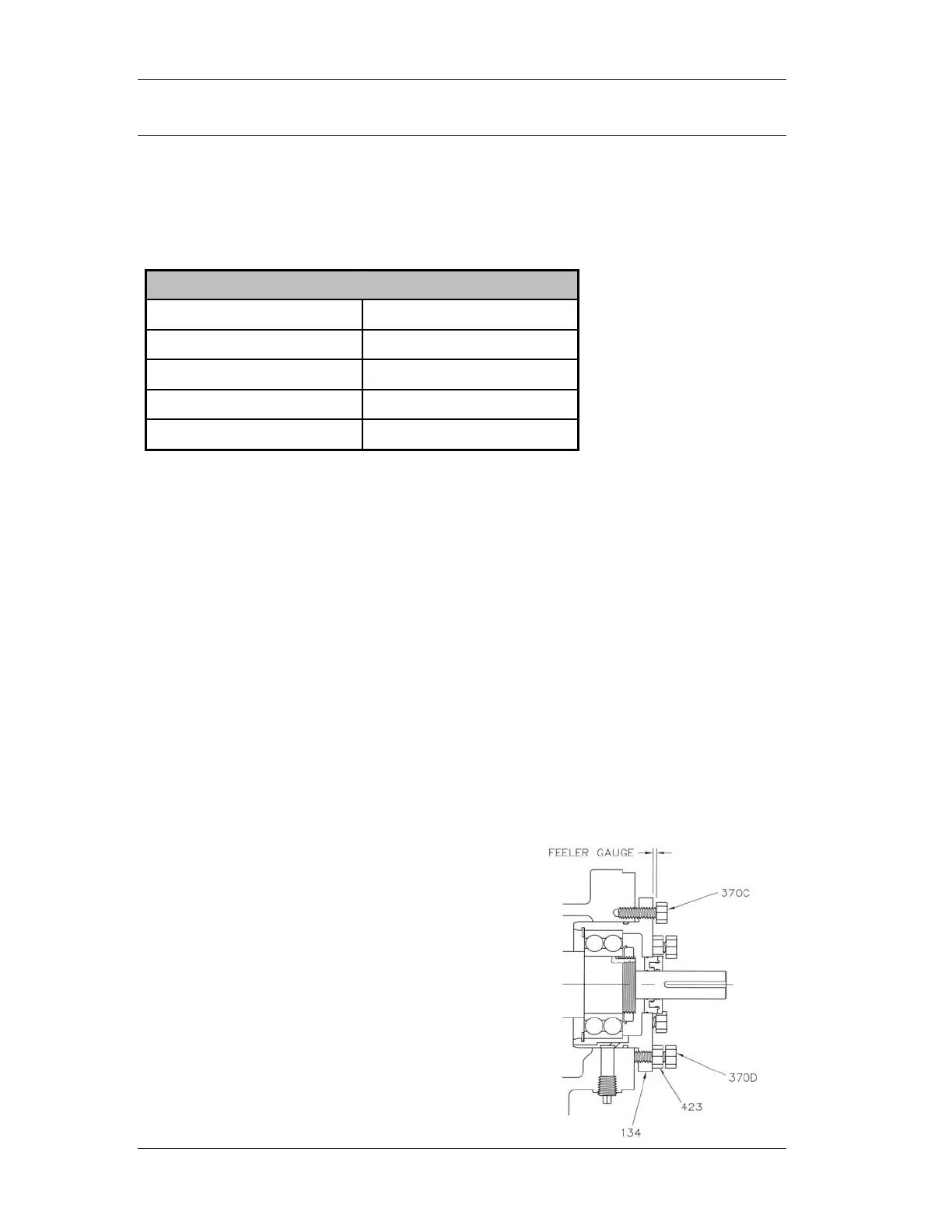
FEELER GAUGE TECHNIQUE
Models 2196, 2196-LF and 2796
TO USE THE FEELER GAUGE TECHNIQUE FOR IMPELLER CLEARANCE SETTING
FOR MODELS 2196, 2196-LF & 2796
1. Lock out power to the pump driver.
2. Remove the coupling guard.
3. Loosen jacking bolts (370D) and jam nuts (423).
4. Tighten bearing housing bolts (370C) evenly, while slowly rotating the shaft until
the impeller starts to rub on the casing.
5. Using a feeler gauge, set the gap between the 3 housing bolts (370C) and the
bearing housing (134). (Refer to Table 6 for settings.)
6. Tighten jack bolts (370D) evenly until bearing housing backs out and contacts the
bearing housing bolts (370C).
7. Tighten jam nuts (423) evenly, rotating the shaft to make sure the assembly turns
freely.
8. Reinstall the coupling guard.
9. Unlock power to the pump driver.