Installation, Operation, and Maintenance Manual
SUMMIT PUMP MODEL 2196 / 2196-LF / 2196-R / 2796 41
APPENDIX H – ANSI B15.1 COUPLING GUARDS
INSTALLATION INSTRUCTIONS FOR SUMMIT PUMP
ANSI B15.1 COUPLING GUARDS
WARNING!
Before assembling or disassembling the coupling guard, de-energize the
motor, lock out the motor controller/starter, and place a caution tag at
the starter indicating that it is disconnected. Before resuming normal
pump operation, replace the coupling guard. Summit Pump assumes no
liability when these procedures are avoided.
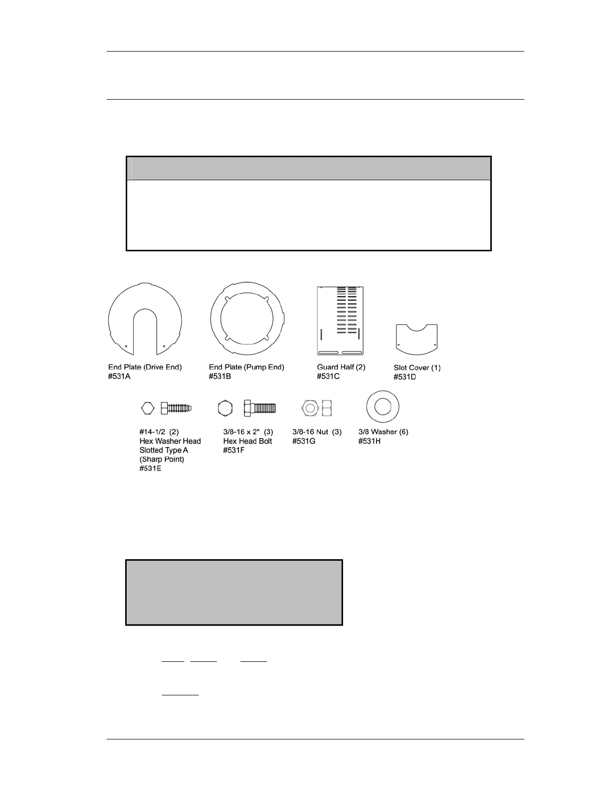
Figure H-1
The design’s simplicity allows complete coupling guard assembly, including the end
plate (pump end), in about fifteen minutes.
ASSEMBLY PROCEDURES
TO ASSEMBLE YOUR COUPLING GUARD
NOTE: If the end plate (pump end) was
previously installed, make any
necessary adjustments to the
coupling and skip to Step 2.
1. On the STO, MTO, and LTO, align the end plate (pump end) to the bearing
frame. (Impeller adjustment is not required.)
On the XLO-X
, align the end plate (pump end) to the pump bearing housing with
the small slots on the end plate aligned to the impeller adjusting bolts and the
large slots clearing the bearing housing tap bolts. Then attach the end plate to the