Installation, Operation, and Maintenance Manual
42 SUMMIT PUMP MODEL 2196 / 2196-LF / 2196-R / 2796
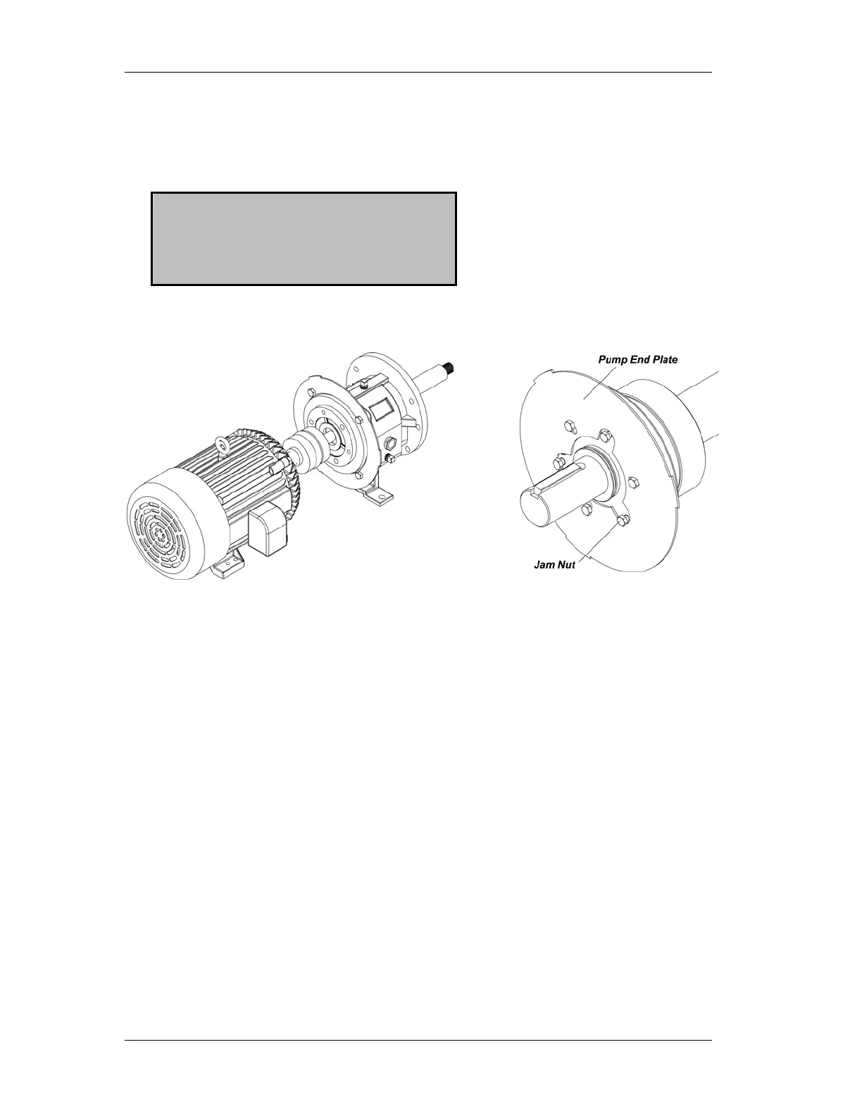
bearing housing using the jam nuts on the impeller adjusting bolts as shown in
Figure H-3.
After attaching the end plate to the bearing housing, check and reset the impeller
clearance as detailed in APPENDIX A - IMPELLER CLEARANCE SETTING.
NOTE: Complete the coupling
adjustments before proceeding
with the coupling guard
assembly.
Figure H-2
STO, MTO, LTO
Figure H-3
XLO-X
2. Slightly spread the bottom of the coupling guard half (pump end) and place it over
the pump end plate as shown in Figure H-4. The annular groove in the guard half
is located around the end plate. (See Figure H-5.)