Installation, Operation, and Maintenance Manual
SUMMIT PUMP MODEL 2196 / 2196-LF / 2196-R / 2796 43
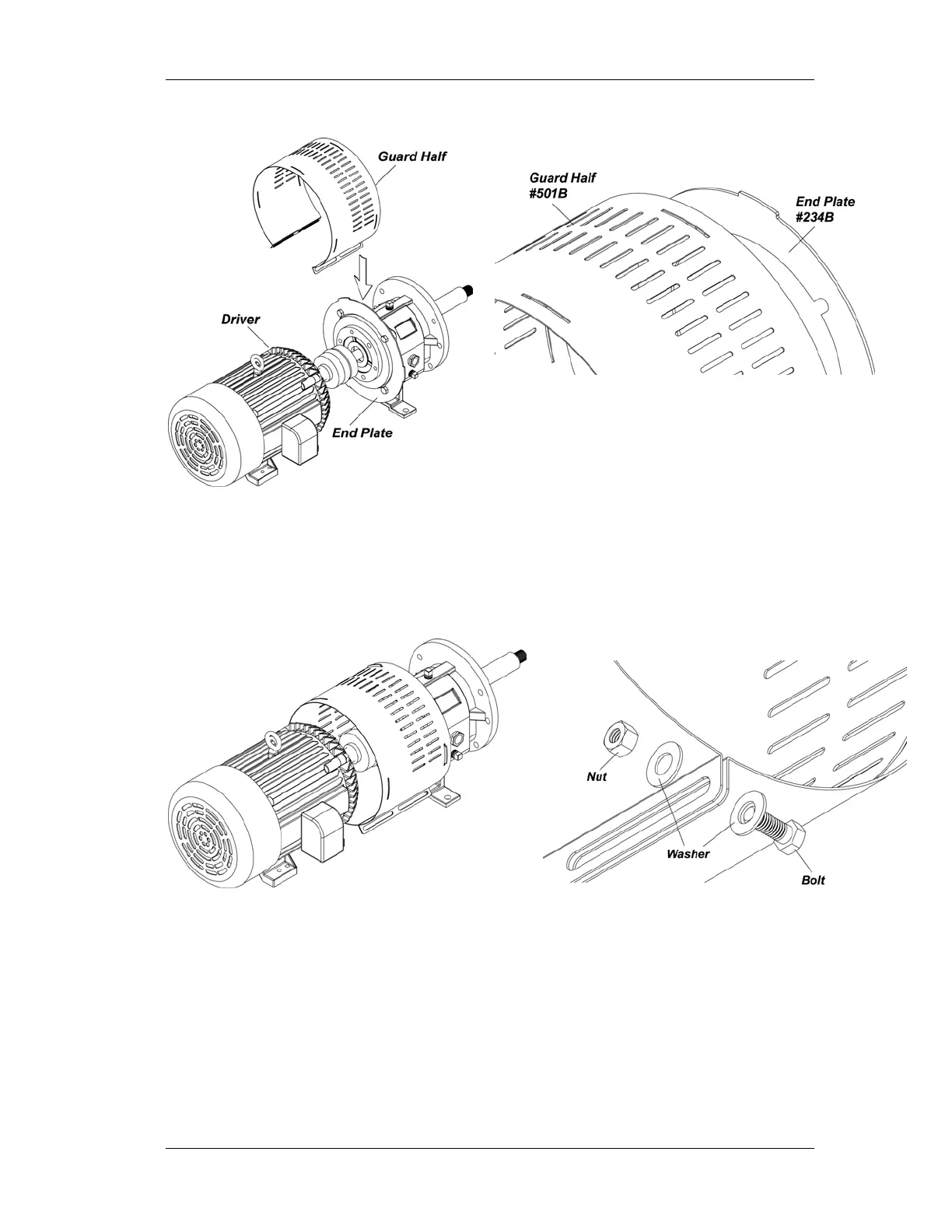
Figure H-4
Figure H-5
3. After placing the coupling guard half (pump end) around the pump end plate,
secure it with a bolt, nut and two (2) washers through the round hole in the front
end of the guard half as shown in Figure H-6. Tighten securely. (See Figure
H-7.)
Figure H-6 Figure H-7
4. Slightly spread the bottom of the coupling guard half (driver end) and place it
over the coupling guard half (pump end) so that the annular groove in the
coupling guard half (driver end) faces the motor as shown in Figure H-8.