Installation, Operation, and Maintenance Manual
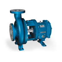
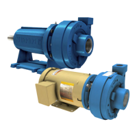
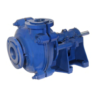
SUMMIT PUMP MODEL 2196 / 2196-LF / 2196-R / 2796 32
APPENDIX E – MAINTENANCE INSTRUCTIONS FOR INPRO/SEAL
®
“VBX” BEARING ISOLATORS
DETAILS OF OPERATIONS
The Inpro Bearing Isolator is a Labyrinth type seal, which performs two functions:
1. Maintains the clean oil in the bearing housing.
2. Keeps contaminates from entering the bearing housing.
The unit is comprised of three major components: the rotor, the stator, and the
“VBX”
®
ring.
The rotor fits over the shaft and is held in place by an elastometric drive ring. The
drive ring causes the rotor to turn with the shaft and also provides a positive static
seal on the shaft. There is no metal-to-metal contact between the shaft and rotor, thus
no wear and friction concerns.
The stator is held in the housing by a nominal .002” interference fit. An o-ring
gasket on the outside diameter of the stator secures a positive seal between the stator
and the housing bore. The designed Labyrinth grooves and lube return trough on the
stator inside diameter retains the lubricant inside the bearing housing.
The rotor and stator act together to keep contamination out of the bearing housing.
The “VBX”
®
ring, stator, and rotor are a unit and must not be pulled apart. If the unit
is pulled apart or comes apart, it must be replaced with a new unit. The “VBX”
®
is
intended to be an inseparable design.
Repairs or replacement of seals are only necessary if excessive oil leakage is visible.
If or when the bearing housing is disassembled, it is recommended that the rotor o-
rings be replaced.
DISASSEMBLY PROCEDURES
1. Remove shaft assembly (122) per instructions for pump disassembly. (See page
18.)
2. STO removal. Insert a bar (wood or plastic) through the outboard bearing
housing end of the bearing frame (228). Contact the inboard bearing isolator
(333A). Remove by tapping the bar or pushing with an arbor press.
MTO and XLO
removal. Disassemble the bearing frame adapter (108) per pump
disassembly instructions. Remove the inboard bearing isolator (333A) with a bar
(wood or plastic) by tapping or by pushing with an arbor press.
3. STO, MTO, and XLO outboard bearing isolator (332A) removal. Block up the
outboard bearing housing (134) on the bench, coupling the end toward the bench
top. Tap the isolator out of the housing or use an arbor press.
4. Inspect the bearing isolators. If the unit pulls apart, a new isolator is needed for
reassembly.
5. Replace the rotor 0-rings and stator 0-rings each time the units are removed from