Installation, Operation, and Maintenance Manual
SUMMIT PUMP MODEL 2196 / 2196-LF / 2196-R / 2796 33
the pump assembly.
INSTALLATION PROCEDURES
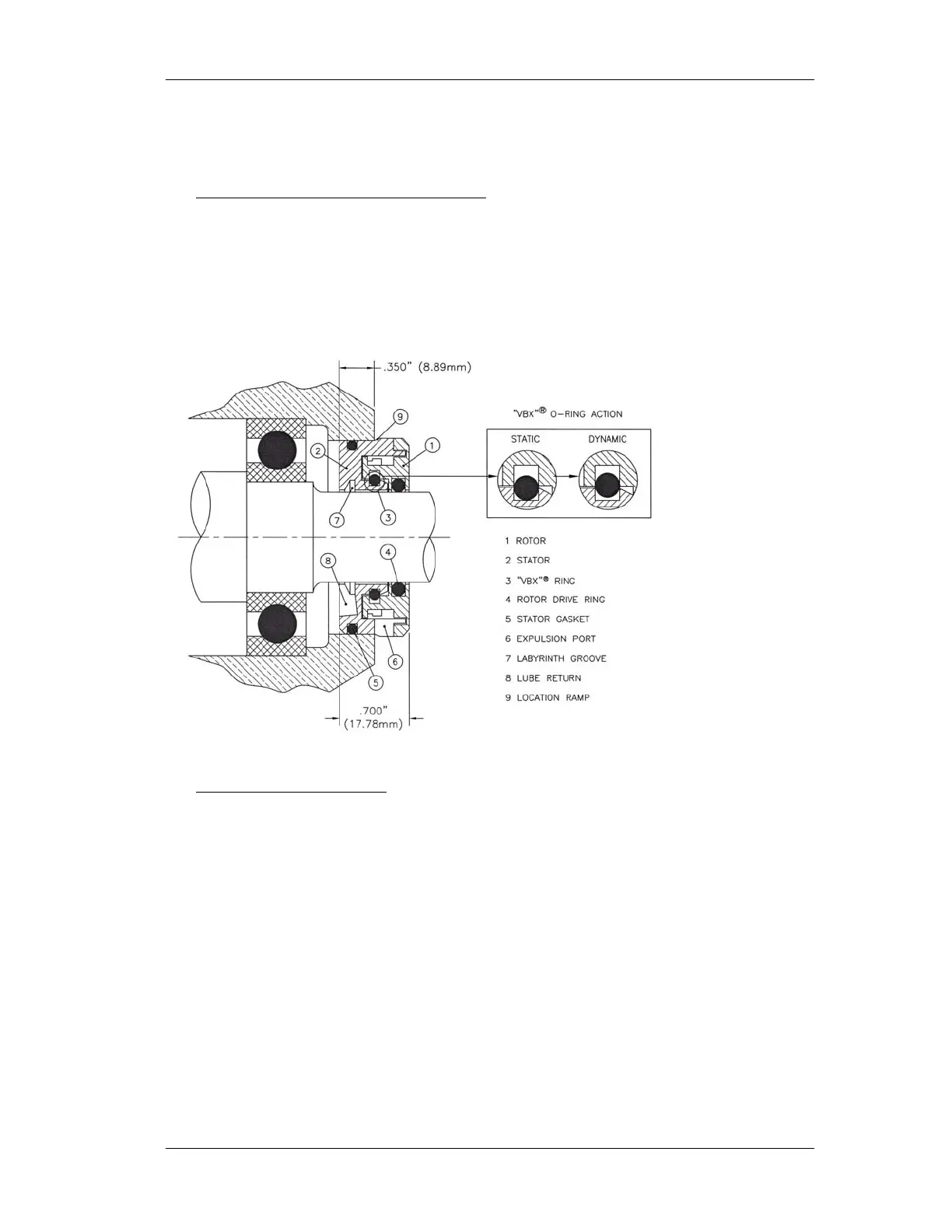
1. STO, MTO, and XLO Inboard Isolator. Position the bearing frame (228) or
adapter (108) inboard bearing side up. Place the isolator seal (333A) stator side in
the bore. THE EXPULSION PORT MUST BE IN THE 6 O’CLOCK
POSITION. While using a block large enough to cover the entire flange of the
isolator, use an arbor press to press the stator into the bore. Press into place until
the location ramp begins. (See Figure 1.)
Figure 1
2. Outboard Isolator (332A)
. Position the bearing housing (134) outside flange up.
Place the isolator in the bore and press into place using the same technique as in
Step 1 above.
3. Lightly lube the sleeve end of the shaft and rotor drive ring. Slide the bearing
frame (228) or adapter (108) over the shaft per assembly instructions.
4. To assemble the outboard end, tape the shaft (122) keyway with black tape. Lube
the tape and rotor drive ring. Slide the bearing housing (134) over the shaft (122)
end and continue per assembly instructions.
MAKE SURE EXPULSION PORT AND LUBE RETURN ARE IN THE 6
O’CLOCK POSITION IN FINAL ASSEMBLY.