24 SUNFAR C300
C300 series of non-sensor current vector-control inverter manual
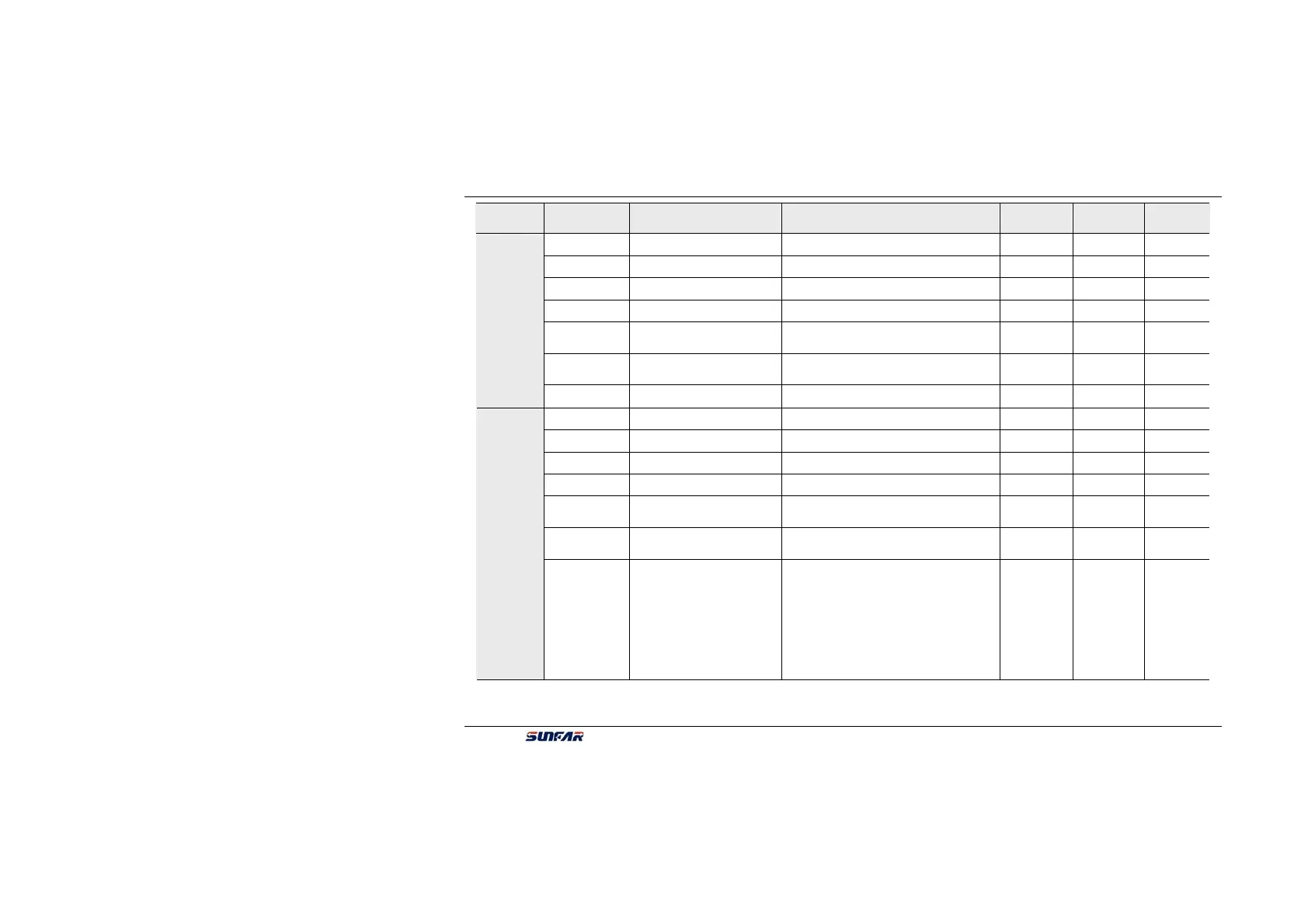
Parameters’
Types
Function Code Name Setting range
Minimum
Setting
Manufacture
Setting
Modify
Limit
F1.24 Stator resistance 0.000~20.000 0.0011 ▲ ★
F1.25 Rotor resistance 0.000~20.000 0.0011 ▲ ★
F1.26
Rotor inductance 0.00~600.00(mH) 0.01 ▲ ★
F1.27 Inductance of excitation 0.00~600.00(mH) 0.01 ▲ ★
F1.28
Leakage inductance
(coefficient)
0.00~100.00(mH) 0.01 ▲ ★
F1.29
Gain of compensation for
speed drop
0.50~1.50 0.01 1.00
Primary applied parameter
unit
F1.30 Reserved
F2.0 Input lower limit voltage VC 0.0 ~ [F2.1] 0.1 0.0V
F2.1 Input upper limit voltage VC [F2.0] ~ 10.0V 0.1 5.0 V
F2.2 Input lower limit current CC 0.0mA~ [F2.3] 0.1 4.0
F2.3 Input upper limit current CC [F2.2] ~ 20.0mA 0.1 20.0
F2.4
Frequency with the min
setting
0.0~[F2.5] 0.01 0.00
F2.5
Frequency with the max
setting
[F2.4]~550.0Hz 0.01 50.00
Analog I/O parameter unit
F2.6
Characteristics selection of
input channel
The first part of LED (form right to left):
(VC channel)
0: positive characteristics
1:Negative characteristics
The second part of LED:Reserved
The third part of LED:(CC channel)
0: positive characteristics
1:Negative characteristics
The fourth part of LED:Reserved
1 0000 ★
 Loading...
