SUNFAR C300 61
C300 series of non-sensor current vector-control inverter manual
Braking
torque
level
f
t
t
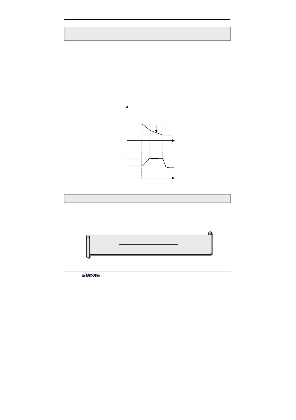
Modified Dec time
It is used for setting permissible output level of torque current under motor
acceleration state.
The restriction on torque level is set by F4.11. It is percentage of rated current of
inverter. For example, F4.11 set 150% that means the max output current is 150
percentage of rated current.
When output current of inverter is beyond setting value of F4.11, inverter will
prolong Acc/Dec time to inhibit output current in setting value of F4.11. Shown as
fig6-19.
It fits for occasions that demand high performance with braking torque. If setting
value of parameter F4.12 is big, the Braking effect will obvious. But inverter will
alarm about over voltage if inverter is not connect braking resistance.
The parameter is used for setting the sensitivity of thermal relay protection for
applied motor. When the rated current of applied motor doesn’t match with the
rated current of inverter, it can accomplish the correct heat protection for the motor
to set this parameter.
The setting value of this parameter can be set by the following formula:
图 6-19 加速力矩与制动力矩示意图
F4.11 Acc torque level Setting range:110 ~ 200 (%)
F4.12 Braking torque lever Setting range:10 ~ 150 (%)
F4.13 Motor over-lode protection coefficient Setting range:50 ~ 110(%)
Fig6-19 Acc torque level
[F4.13]= ×100%
Rated current of motor
Inverter’s rated output current