62 SUNFAR C300
C300 series of non-sensor current vector-control inverter manual
The function of Automatic voltage regulation is to ensure the output voltage of
inverter not to fluctuate with the input voltage. When the range of fluctuation of
power supply voltage is too large, and expect to motor have the stabilized stator
voltage and current, this function should be open.
0:Invalid 1: Dynamic valid 2: Static valid
When user selects dynamic voltage regulation, fast dynamic voltage regulation can
inhibit form increasing current cause by DC voltage in motor deceleration. But it
easy brings current resonance.
For getting good performances in vector mode, please set AVR available (F4.14 is
1 or2).
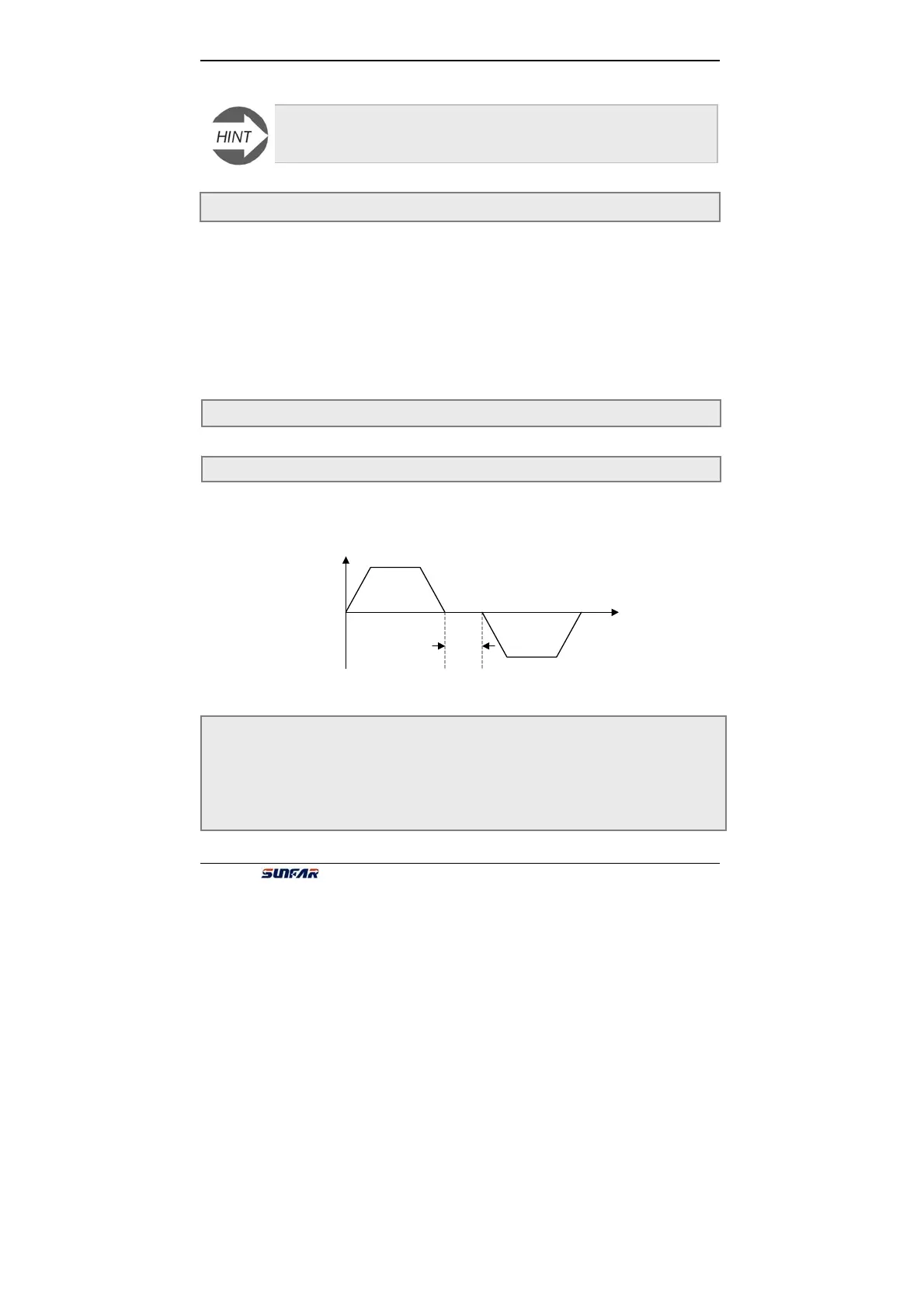
The parameter means that the duration at zero frequency when the inverter
changes its running direction, and it is shown as the following fig.6-20. FWD and
REV dead time is set for the big inertia load which has the mechanical dead zone.
F4.15 Reserved
F4.16 Dead time of FWD&REV Setting time:0.0 ~ 5.0 Sec
F4.17 Acceleration time 2 Setting range:0.1 ~ 6000 Sec
F4.18 Deceleration time 2 Setting range:0.1 ~ 6000 Sec
F4.19 Acceleration time 3 Setting range:0.1 ~ 6000 Sec
F4.20 Deceleration time 3 Setting range:0.1 ~ 6000 Sec
F4.21 Acc time 4/Jog Acc time Setting range:0.1 ~ 6000Sec
F4.22 Dec time 5/Jog Dec time Setting range:0.1 ~ 6000Sec
While one inverter parallel running with multi-motors, the thermal relay protection
of inverter will be invalid, in order to protect the motor, please install the thermal
relay on inlet terminals the motor.
F4.14 Automatic voltage regulation(AVR) Setting range:0 ~ 2
t
[F3.10]
Output frequency
Fig.6-20 Dead zone between FWD and REV
 Loading...
