SUNFAR C300 63
C300 series of non-sensor current vector-control inverter manual
Jog frequency has the highest priority. In any state, as long as Jog instruction is
input, the inverter will transit to run at Jog frequency according to the setting Acc
and Dec time.
It defines rate that terminals UP/DW modify setting freq. Speed of F4.23 isn’t
controlled by Acc/Dec time.
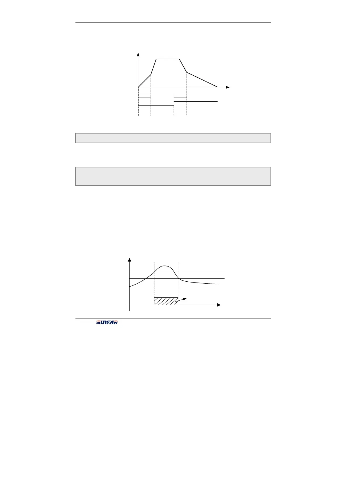
Those parameters are valid for inverter with the inner brake unit. And they define
the action parameter of inner brake unit. When inner DC voltage of inverter is
higher than the start voltage of dynamic braking, the inner brake unit will act. If
inverter connects external brake resistance, DC energy of inverter will be release
by it to decline DC voltage. When DC voltage declines to the certain value
([F3.19]-50V), inner brake unit of inverter will be off, shown as Fig.6-22.
Braking unit action ratio is used for defining the voltage on brake resistor, and the
voltage on brake unit is Voltage PWP. Duty cycle equals brake action ratio. The
ratio is larger, and the energy is consumed more quickly, at the same time, the
power of brake resistor is bigger. User can set parameter according to the
resistance and power of resistor and actual braking effect.
F4.23 Modified rated of UP/DW terminals Setting range:0.01 ~ 100.00 (Hz/Sec)
Fig.6-21 Acc/Dec time selection
f
t
cc/Dec terminal
1
cc/Dec terminal
2
Acc/Dec
time 1
Acc/Dec
time 2
Acc/Dec
time 3
F4.24 Start voltage of dynamic braking Setting range:600 ~ 720 V
F4.25 Action ratio of d
namic brakin
Settin
ran
e:10 ~ 100(%)
Brake unit acts
t
DC
Voltage
[F4.24]
[F4.24]-50V
Fig.6-22 dynamic braking