30
11) Input of the compressed air and control of the air pressure (HA type)
[Caution]
For safety, be sure to turn the power off during adjustments.
[Figure 56]
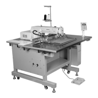
A. Connect the quick joint socket① where pressed air
is connected to, with the quick joint plug② mounted
to the table.
B. Open the finger valve③ to put in the compressed air.
[Note]
When you close the finger valve after use, the remaining
air will be discharged automatically and the remaining
pressure will be indicated as 0 MPa (0kgf/cm
2
)
[Figure 57]
C. Pull the control handle at the upper part of the filter
regulator as shown above and turn it clockwise to increase
pressure and counterclockwise to decrease pressure.
After setting the pressure at 0.49~0.54MPa (5~5.5
kgf/cm
2
) as indicated on the pressure gauge, press back
and fix the control handle to its original position.
[Caution]
If the air pressure drops (under 4 kgf/cm
2
) during use,
the error sign [Er07] will appear and the machine will
stop automatically.
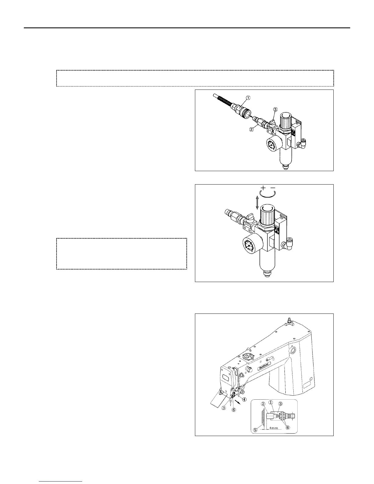
12) Control of the upper thread holding device (optional)
A. Check if the pin cylinder knuckle① and the cap② of
the upper thread holder are positioned at the center
of the upper thread passage.
B. If they are not at the center, loosen two screws④ of
the pin cylinder bracket③ to bring them towards the
center. Fasten the screws afterwards.
C. The recommended distance between the end point
of the knuckle cap② and the ARM⑤ is 4mm.
D. To adjust the clearance, unfasten two pin cylinder
nuts⑥ for adjustment and fasten them afterwards.
[Figure 58]
 Loading...