33
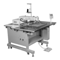
5) Adjustment of the presser foot height
A. For general, thick, thin or knitted materials
Unfasten the screws② of the lift lever control plate on the left and right side of the feed bracket①. When you raise
the control plate③ to the A direction, the height of the presser foot④ will go down and to the B direction, the height
will go up. After fine-tuning the height, securely tighten the screws②.
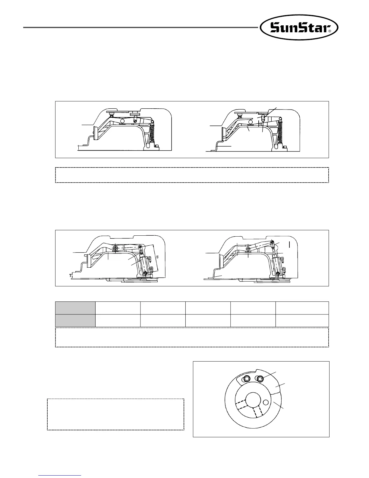
B. For air-pressure type (HA type)
Unfasten the cylinder knuckle nut③ attached to the left and right cylinder② of the feed bracket①. When you turn
the cylinder axis④ to move the cylinder knuckle⑤ up towards the A direction, the height of the presser foot⑥ will
decrease, and when you move it down towards the B direction, the height will increase. After adjustments, securely
fix the cylinder knuckle nut③.
The value of cylinder adjustment to presser foot height
[Figure 64]
[Figure 65]
[Caution]
Fasten all the screws tightly after adjusting the height of the presser foot.
[Caution]
When adjusting the presser foot height over the maximum value (14mm), be sure to remove the wiper unit.
6) Adjustment of thread release-related parts
A. Setting the position of the thread release notch
Place the notch so that the right side of a slot of the
thread release notch① touches the circumference of
the notch screw②, and fix with a screw.
[Figure 66]
[Caution]
If the positioning is not correct, the remaining length of
the thread may be too short or inconsistent, and/or the
thread may come out of the needle when sewing starts.
①
Thread Trimmer Cam
②
↓
↑
Max. 17mm
③
①
A
B
④
②
①
⑤
④
⑥
③
②
A
B
T
14
85.4
15
84.5
16
83.7
17
82.8
18
82.0
S
 Loading...