39
11) Positioning of the synchronizer (C-Series)
A. Installing the synchronizer
ⓐ Mount the synchronizer onto the backside of the
arm.
ⓑ Set a clearance between the pulley and the
synchronizer at 2.5mm, and then fasten the screw.
[Figure 80]
Upper Shaft
Busing(Rear)
Synchronizer
Upper Shaft
Pulley
2.5mm
Pulley
Screw
Magnetic
Holder
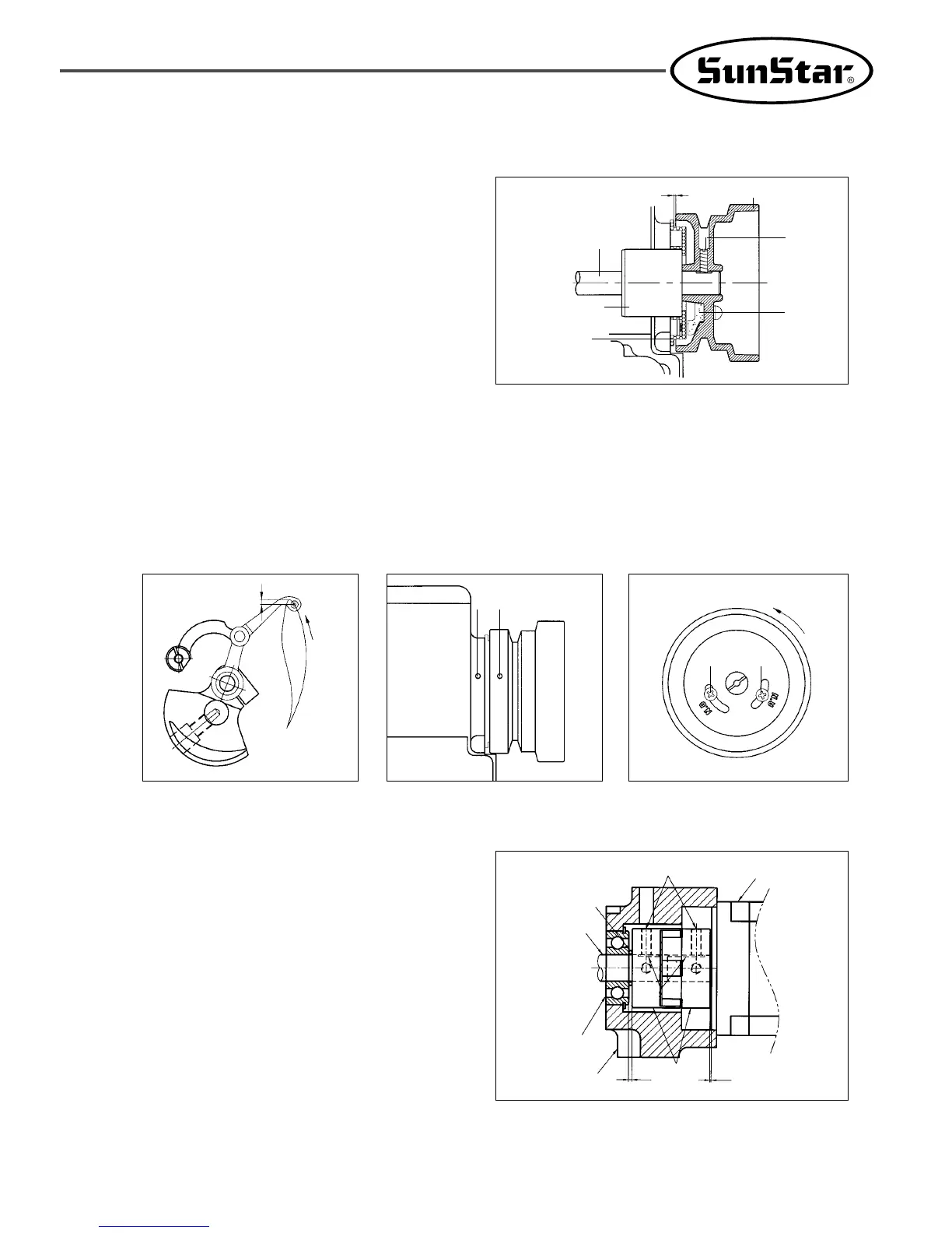
B. Adjusting the position of the synchronizer (position detector)
ⓐ Turn the pulley to adjust the position of the thread take-up lever as shown in the Figure. At this point, the white
carved slot of the pulley should be parallel to the white carved slot of the arm.
ⓑ Adjust the screw① on the carved N.U sign in the pulley until the carved point of the pulley and the carved
point of the arm meet, and fasten the screw①.
ⓒ Unfasten and move the screw② of the carved N.D sign left and right. Position the screw at a point where the
needle bar just starts to ascend from its lowest position.
[Figure 82][Figure 81]
Direction
Of
Rotation
About 3mm
[Figure 83]
Direction
Of
Rotation
①②
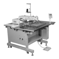
12) Installation and control of the direct drive motor (D-Series)
A. To mount the coupling onto the Servo motor, accurately
place the screw no. 1 of the coupling on the flat surface
area of the Servo motor. Set a clearance between the
coupling and the Servo motor at 0.7mm, and then fasten
the screw.
B. To mount the coupling onto the upper shaft, accurately
place the screw no. 1 of the coupling on the flat surface
area of the upper shaft, and press it firmly towards the O-
ring of the upper shaft rear bearing, leaving a clearance
of 2mm. Then fasten the screw no. 1 of the coupling.
C. When binding the two couplings together, make sure that
each screw of the couplings is aligned with each other.
※ If the coupling screws are not aligned with each other,
the needle will not stop in normal position.
[Figure 84]
Screw No. 1
Flat Surface
Coupling
Servo Motor
O-ring
Upper Shaft
ARM
2 0.7
Upper Shaft
Rear Bearing
 Loading...