16
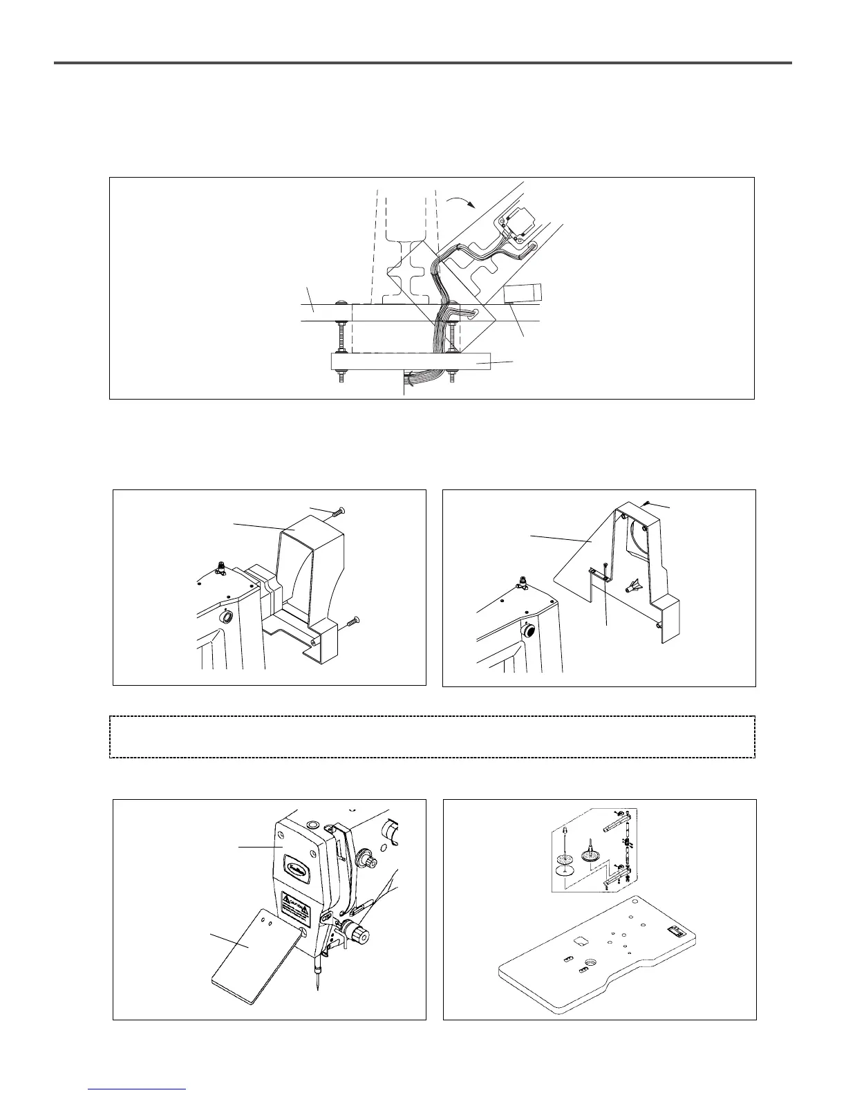
B. Attach the safety plate to the backside of the arm.
[Figure 19]
Safety Plate
Assembly
Faceplate
[ Caution ]
For safety, motor cover and safety plate should be attached to the machine.
C. Install the thread stand onto the table.
[Figure 20]
5) The assembly of peripheral parts
A. Attach the motor cover to the top (2EA) and bottom (2EA) of the back side of machine and sides by using fixing bolts.
(In case of C series, attach the belt cover by using fixing screws for the rear (3EA) and the side (2EA).)
[Figure 17]
[Figure 18]
Motor Cover
Velt Cover
Fixing
Screw
C-seriesD-series
Fixing Screw
Fixing Screw
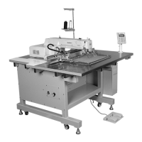
I. Complete the cabling connection between the machine and the control box and fix the cables below the table as in
the figure. (When the machine should be erected to fix the cables, set the length of the cables considering the
machine erection.)
[Figure 16]
Table (above)
Table (below)
Hinge
 Loading...