41
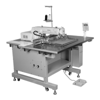
14) Adjustment of the vent hole device
[SPS/D(C)-B1201M (HP)]
A. Unfasten the screw② of the pin plate A①. With your
finger, push “M” part up and down to adjust the pin
plate A①. The pin A③ should move vertically at the
center of the needle plate groove. Tighten with a
screw② afterwards.
15) When the vent hold device is not used
[SPS/D(C)-B1201M (HP)]
A. Check if the supporting plate of the stopper① is
facing inside. Adjust the stopper① up and down to
lower the pin A② below the needle plate. Fix with a
screw afterwards.
[Figure 87]
[Figure 88]
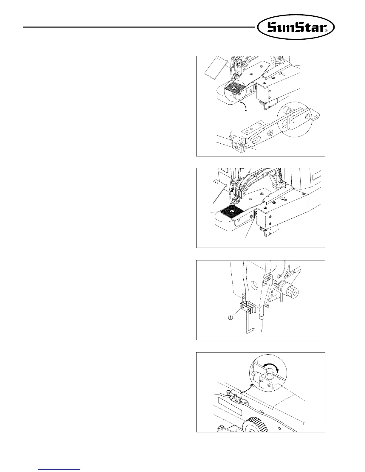
16) Adjusting and operating the needle cooler
A. Adjusting the nozzle
Loosen two fixing screws ① only a little bit as shown
in the figure. Set the nozzle in an optimal position and
firmly tighten it back with the screws.
The needle cooler moves simultaneously with the
presser foot. When the presser foot begins to descend,
operate the needle cooler and when the presser foot
begins to ascend, stop the needle cooler.
[Figure 89]
B. Adjust the amount of air with the speed controller
attached on the left part of the arm as shown in the
figure. Refer to the figure for adjustments.
[Figure 90]
①
(+)
(-)
Pin A③
Screw②
Pin Plate
A①
“M”
Pin A
②
Stopper①
 Loading...