OPERATION OF THE MJB4
16 MJB4 - Operation Rev02 01-06
3
3.1. Definitions
3.1.1. Notations
You should be familiar with the following definitions
when reading this manual. The name of a control or
display is written in capital letters in the text below.
For example, the word:
SETTINGS
refers to the key in the display that has the same
label. Instructions and prompts that appear in the
display are written in quotation marks. For example:
“Microscope Up”
A warning for the machine operator is written in bold.
For example:
Warning! Microscope movement!
Each control and display has a unique number. The
first digit of this number corresponds to the number
of the figure where the element is displayed. For
example:
204. VACUUM Manometer
This means the element with the Vacuum label is a
display, is the fourth element that is described and is
shown in figure 2.
This manual explains how to use the machine as a
mask aligner.
3.1.1.1. Coordinate System
The unit for position specifications in the X and Y
directions is millimeters. The unit for position
specification in the Z direction is micrometers. The
specifications refer to a coordinate system whose X
and Y origin is the center of the adjusting station.
The zero point of the Z axis is in the active mask
level or the upper substrate level.
Coordinate system
3.2. Controls and Displays
Main switch with emergency off function
This switch connects or disconnects the mask
aligner and ballasts to or from the power supply
network.
In the event of danger, turn the switch to the OFF
position.
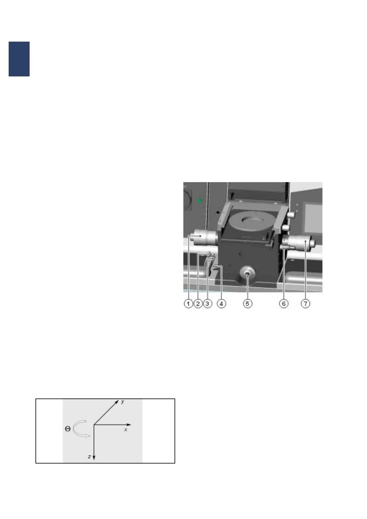
3.2.1. Adjusting Table
Adjusting table with coordinate system
1 Table – Y motion
2 Separation lever
3 Adjusting distance setting
4 Contact lever
5 Variable thickness setting
6 Table – theta motion
7 Table – X motion
Table - X Motion
This micrometer screw is located on the right side of
the adjusting table and moves the substrate in the X
direction. The travel path is ±5 mm.
Table - Y Motion
This micrometer screw is located on the left side of
the adjusting table and moves the substrate in the Y
direction. The travel path is ±5 mm.