ENGINE GENERAL INFORMATION AND DIAGNOSIS (M13 ENGINE) 6-2-101
DTC P0136 O2 Sensor (HO2S) Circuit (Sensor-2)
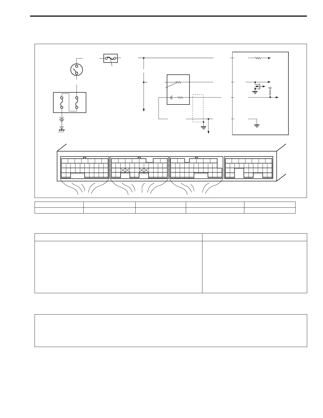
Wiring Diagram
DTC Detecting Condition and Trouble Area
DTC Confirmation Procedure
1. Relay box 3. Ignition switch 5. “IG COIL” fuse 7. Heater 9. ECM
2. Shield wire 4. Circuit fuse box 6. HO2S–2 8. To HO2S–1 heater 10. To other sensor
E23 E22 E21
12345671234561234567
7
891011121314151617 8910111213141516 891011121314151617
1819
1819
1718192021222324252627 20212223 202122232425 24252627 2627
2829303132 32 282930 28293031 3133 33 323334 3435 3435
BLK/WHTBLK/WHT
WHT/BLU
80A
60A
BLU/BLK
BLU
BRN/WHT BRN/WHT
BLU/RED
BLK/WHT
BLK/WHT
E21-28
E23-3
E22-33
E22-28
5
1
3
4
6
8
10
2
9
7
DTC Detecting Condition Trouble Area
DTC will set when one of the following conditions is detected.
• Maximum output voltage of HO2S–2 is lower than specified value
or minimum output voltage is higher than specified value while
vehicle driving.
• Engine is warmed up and HO2S–2 voltage is higher than speci-
fied value (circuit open)
(2driving cycle detection logic)
• HO2S–2
• HO2S–2 circuit
• Fuel system
• ECM
• Fuel shortage
• Exhaust gas leakage
WARNING:
• When performing a road test, select a place where there is no traffic or possibility of a traffic acci-
dent and very careful during testing to avoid occurrence of an accident.
• Road test should be carried out with 2 person, a driver and tester, on a level road.
NOTE:
Check to make sure that the following conditions are satisfied when using this DTC CONFIRMATION
PROCEDURE.
• Intake air temp.: –7°C, 19.4°F or higher
• Engine coolant temp.: 70°C, 158°F or higher
• Altitude (barometric pressure): 2500 m, 8200 ft or less (540 mmHg, 72 kPa or more)
 Loading...