ENGINE GENERAL INFORMATION AND DIAGNOSIS (M13 ENGINE) 6-2-127
DTC P0480 Fan 1 (Radiator Cooling Fan) Control Circuit
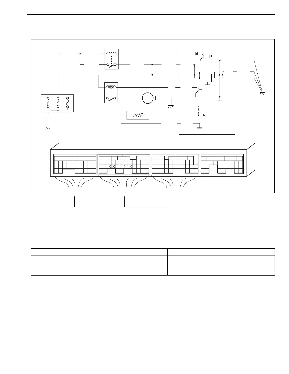
Wiring Diagram
Circuit Description
Radiator fan relay is controlled by ECM if ECT is specified value.
When A/C condenser fan motor is running while head light is turned ON and engine is running at below 1500 r/
min, radiator fan relay is turned OFF for 2 sec. by ECM.
DTC Confirmation Procedure
1) Turn ignition switch turned OFF.
2) Clear DTC with ignition switch ON.
3) Warm up engine until radiator cooling fan starts to operate.
4) Check pending DTC in “ON BOARD TEST” or “PENDING DTC” mode and DTC in “DTC” mode.
1. Relay box 3. Radiator fan relay 5. ECT sensor
2. Main relay 4. Radiator fan motor 6. ECM
E23-15
12V
5V
E21-6
E21-5
BLK/REDBLK/RED
BLK/RED
80A
BLK/YEL BLK/YEL
BLK/YEL
BLU/BLK
E22-1
E23-2
BLK/YEL
BLK/YEL
BLK
E23-1
E23 E22 E21
12345671234561234567
7
891011121314151617 8910111213141516 891011121314151617
1819
1819
1718192021222324252627 20212223 202122232425 24252627 2627
2829303132 32 282930 28293031 3133 33 323334 3435 3435
20A 30A
BLK/YEL BLU/RED BLK
BLU
E21-4
E22-16
YEL/GRN
BRN/WHT
E22-28
BLK/RED
1
2
6
3
4
M
5
DTC Detecting Condition Trouble Area
• Monitor signal of radiator fan relay is different from com-
mand signal.
•“BLK/RED” or “BLU” circuit open or short
• Radiator fan relay malfunction
• ECM malfunction
 Loading...