6-2-152 ENGINE GENERAL INFORMATION AND DIAGNOSIS (M13 ENGINE)
Table B-2 Fuel Pump and Its Circuit Check
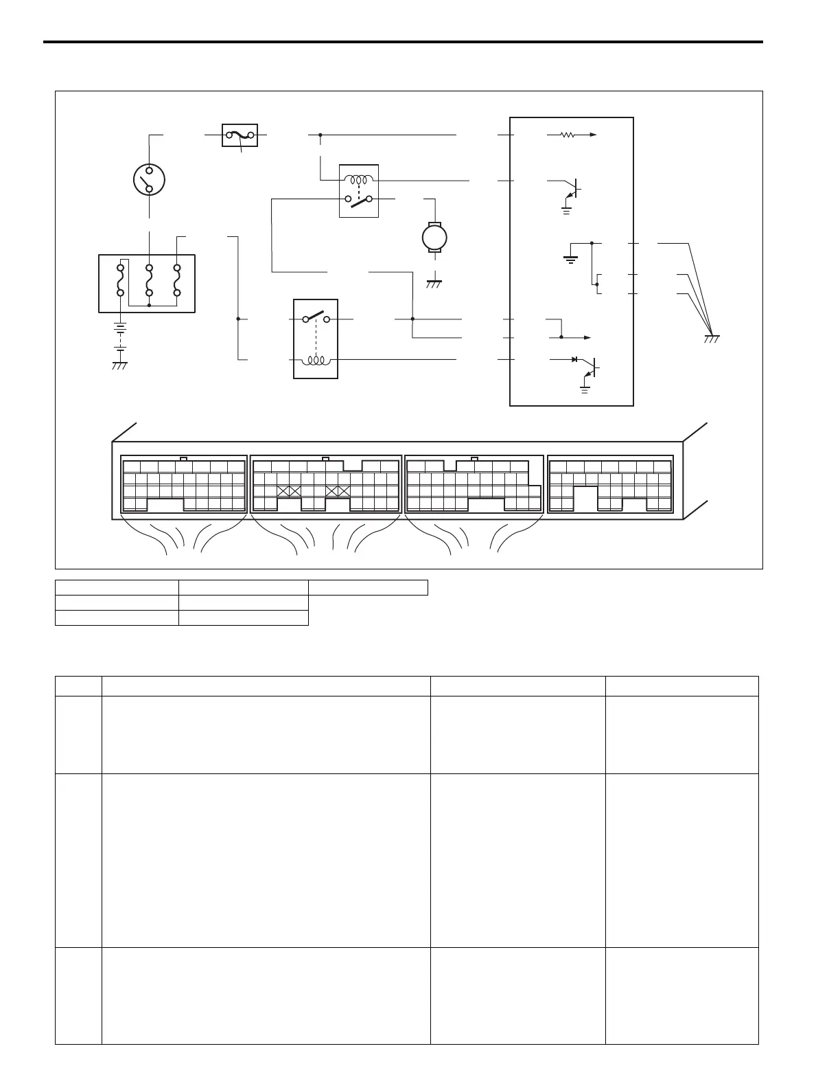
Troubleshooting
1. Relay box 4. Fuel pump relay 7. Ignition switch
2. Main relay 5. Fuel pump
3. ECM 6. “IG COIL” fuse
Step Action Yes No
1 Check fuel pump control system for operation. See
Fig.1.
Is fuel pump heard to operate for 3 sec. after igni-
tion switch ON?
Fuel pump circuit is in
good condition.
Go to Step 2.
2 Check fuel pump relay power supply.
1) Disconnect fuel pump relay from relay box with
ignition switch turned OFF.
2) Check for proper connection to fuel pump relay
at each terminals.
3) If OK, turn ON ignition switch, measure voltage
between “BLK/WHT” wire terminal and engine
ground.
Is voltage 10 – 14 V?
Go to Step 3. “BLK/WHT” wire open
or shorted to ground
circuit.
3 Check fuel pump relay power supply.
1) Turn ON ignition switch, measure voltage
between “BLK/RED” wire terminal of fuel pump
relay connector and engine ground.
Is voltage 10 –14 V?
Go to Step 4. “BLK/RED” wire open
circuit.
E21-6
E23-15
E21-5
E23-14
BLU/BLK
BLK/RED
BLK/RED
BLK/YEL
BLK/YEL
BLK/RED
BLK/RED
80A
60A 20A
E21-28
BLK/WHTBLK/WHT
BLK/WHT
GRN
PNK
BLK
WHT/BLU
BLU/BLK
E21-1
E23-2
BLK/YEL
BLK/YEL
BLK
E23-1
BLK/YEL
E23 E22 E21
12345671234561234567
7
891011121314151617 8910111213141516 891011121314151617
1819
1819
1718192021222324252627 20212223 202122232425 24252627 2627
2829303132 32 282930 28293031 3133 33 323334 3435 3435
1
7
6
4
3
2
5
 Loading...