A-96.250.511 / 091120
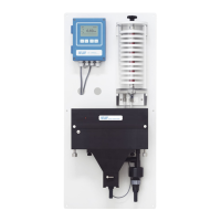
AMI Turbiwell
Installation
20
3. Installation
3.1. Installation Checklist
On-site
requirements
AC variant: 100–240 VAC (10%), 50/60 Hz (5%)
DC variant: 10–36 VDC
Power consumption: 35 VA maximum.
Protective earth connection required.
Sample line with sufficient sample flow and pressure (see Instrument
Specification, p. 14).
Installation Mount the instrument in vertical position.
Display should be at eye level.
Connect the sample inlet and waste lines.
Adjust the measuring chamber to horizontal position with the adjust-
ing screw. Check with spirit level.
Electrical Wiring Do not switch on the Instrument until all electrical connections have
been made.
Connect all external devices like limit switches, current loops and
pumps, see Connection Diagram, p. 38.
Connect power cord.
Power-up Turn on the sample flow and wait until the measuring chamber is
completely filled.
Switch on power.
Instrument
Setup
Program all parameters for external devices (interface, etc.).
Program all parameters for instrument operation (limits, alarms).
Run-in time Let the instrument operate for 24 h without interruption at normal
sample conditions to rinse out any pollution from manufacturing and
transport.
Matching Each verikit has to be matched with the current calibration values
before it can be used for a verification.
Verification Never perform before the run-in time is over and before the mea-
sured value is stable.
Can be performed to verify the device functions.
 Loading...