A-96.250.511 / 091120
AMI Turbiwell
Installation
29
3.5. Installation of Flowcontroller Option
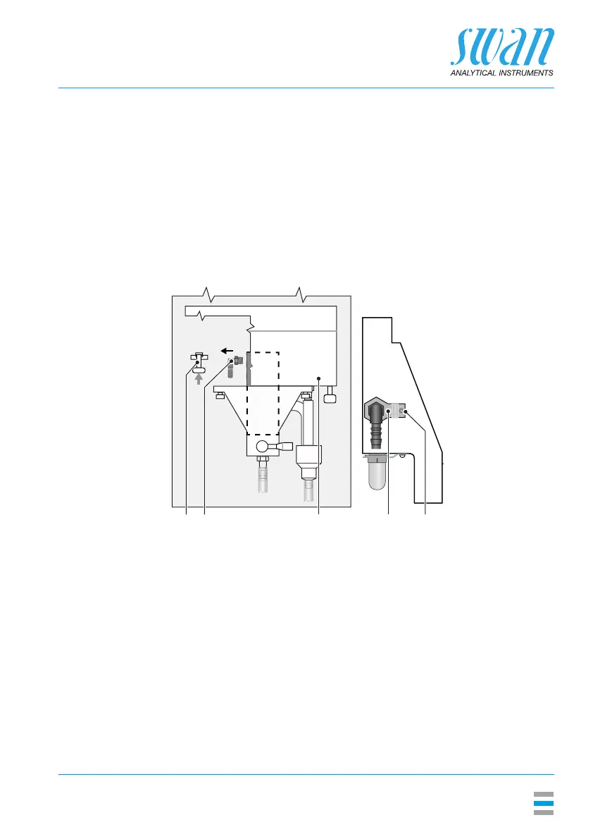
Preparations 1 Push the locking pin [D] upward to unlock the measuring
chamber.
2 Swivel the measuring chamber [G] out.
3 Remove the sample inlet tube from the elbow hose nozzle [A].
4 Unscrew and remove the screw [J].
5 Remove the locking plate [I].
6 Unscrew the elbow hose nozzle [A] from the constant head.
A
D
G
Elbow hose nozzle
Locking pin
Measuring chamber
I
J
Locking plate
Screw
 Loading...