A-96.250.511 / 091120
AMI Turbiwell
Program List and Explanations
93
5 Installation
5.1 Sensors
5.1.1 Sensor type: Display of the used sensor type (e.g. Well IR)
5.1.2 Dimension: Choose the measurement unit (FNU, NTU or ppm)
5.1.3 Flow: Select a flow measurement method.
5.1.3.1 Flow measurement: Select the type of flow sensor if a flow sensor is
installed. Possible flow sensors:
5.3.1.2 Slope: Only available if deltaT flow has been selected. Increase or
decrease the slope to adjust the sample flow, see Adjusting the del-
taT Flow Sensor (Option), p. 46.
5.1.4 Offset: A manual offset of the measured value can be set.
Range: -1.000 to +1.000 FNU/NTU
5.2 Signal Outputs
Note: The navigation in the menu <Signal Output 1> and <Signal
Output 2> is equal. For reason of simplicity only the menu
numbers of Signal Output 1 are used in the following.
5.2.1 & 5.2.2 Signal Output 1 & 2: Assign process value, the current loop range
and a function to each signal output.
5.2.1.1 Parameter: Assign one of the process values to the signal output.
Available values: Meas. value, Sample flow.
5.2.1.2 Current Loop: Select the current range of the signal output.
Make sure the connected device works with the same current range.
Available ranges: 0–20 [mA] or 4–20 [mA]
5.2.1.3 Function: Define if the signal output is used to transmit a process
value or to drive a control unit. Available functions are:
Linear, bilinear or logarithmic for process values.
See As process values, p. 94
Control upwards or control downwards for controllers.
See As control output, p. 95
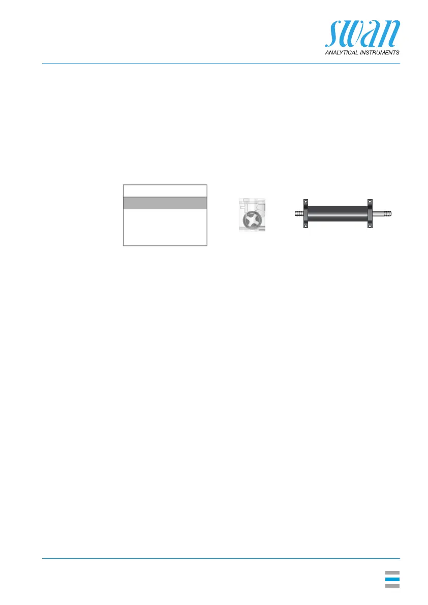
Flow measurement Q-Flow / Q-HFlow deltaT
None
Q-Flow
Q-HFlow
deltaT
 Loading...