EasyManuals Logo

SYMC BC360 User Manual

SYMC BC360
63 pages
To Next Page IconTo Next Page
To Previous Page IconTo Previous Page
Page #12 background imageLoading...
Page #12 background image
5
4.2.1 Power supply
BC360.XX is powered by a universal power supply that operates 20~28V Power supply
connects to +24V and -24V terminals, never share same power supply with motor, relay,
heater…high voltage equipments..
Pin definition listed as below
pin
description
+24V
Positive power
COM
Negative power
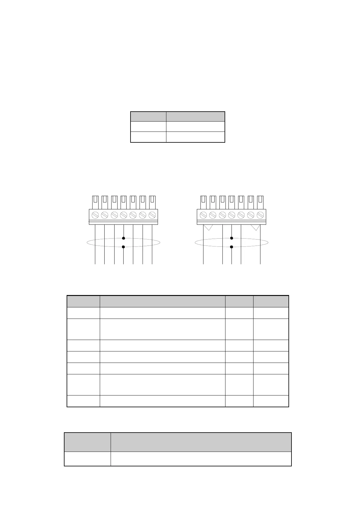
4.2.2 Load cell connection
BC360 is connected with max 6 pcs load cells of 350 ohms,(or load of 58 ohm). Wire
connections as below. When connecting 4 wires load cell, jumper must be placed between +EXC
and +SEN terminal and between
EXC and
SEN terminal.
+EXC
+SEN
+SIG
SHLD
-SIG
-SEN
-EXC
-EXC
-SIG
+SIG
+EXC
SHLD
+SEN
-SEN
Terminal
Description
4 wire
6 wire
+EXC
Positive excitation
Red
Red
+SEN
+Sense terminal. short with +EXC if
connecting 4 wire cell
-
blue
+SIG
positive signal
green
green
SHLD
shield ground
-SIG
negative signal
White
white
-SEN
-Sense terminal. short with -EXC if
connecting 4 wire cell
-
yellow
-EXC
negative excitation
Black
black
4.2.3 series port
That indicator has isolated series ports, R232 & R485 share same terminals.
pin
definition
description
A/TX
RS232Tx
RS485 A+

Questions and Answers:

Question and Answer IconNeed help?

Do you have a question about the SYMC BC360 and is the answer not in the manual?

SYMC BC360 Specifications

General IconGeneral
BrandSYMC
ModelBC360
CategoryMeasuring Instruments
LanguageEnglish