12713140-002-2 Revision E – October 2006 SSU-2000e User’s Guide 47
Chapter 1 Product Overview
Overview of SSU-2000e Operation
Overview of SSU-2000e Operation
After initial installation and configuration is completed, the SSU-2000e is capable of
unattended operation. After power-up, where the external power supplies are turned
on so that they supply power to the main shelf, the SSU-2000e performs a
self-diagnostic test routine and properly initializes the hardware. Any active Alarms
are time tagged and reported as Events. All Events are time tagged and the last 500
Events are stored in NVRAM. All Events can be cleared by the user with the
appropriate access level. Several optional levels of password protection are
available for system protection as described in Chapter 2, Installing the SSU-2000e.
After the internal oscillators on any installed Clock modules have warmed up, the
SSU-2000e enters the ACQUIRE mode to phase lock the oscillators to the external
references. After the SSU-2000e reaches the LOCKED mode on at least one of the
Clock modules, any change of state is reported as an Event.
Synchronization Status Messages (SSMs)
The SSU-2000e supports input and outputs SSMs. SSMs provide clock quality
information to any equipment that uses synchronization inputs. Table 1-8 describes
the ANSI SSM values and the traceability associated with each value. describes the
ITU SSM values and the traceability associated with each value.
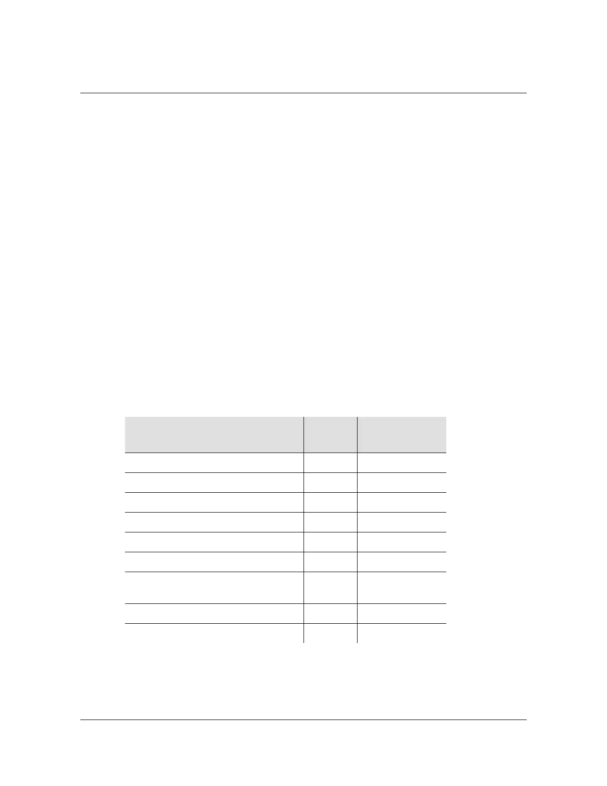
Table 1-8. ANSI SSM Quality Level Definitions
Description
Quality
Level
Abbreviation
Stratum 1 traceable 1 PRS
Synchronized – traceability unknown 2 STU | UNK
Stratum 2 traceable 3 ST2 | TYPE II
Transit Node traceable 4 TNC | TYPE I
Stratum 3E traceable 5 ST3E | TYPE III
Stratum 3 traceable 6 ST3 | TYPE IV
SONET Minimum Clock traceable
(20 ppm clock)
7SMC
Stratum 4 traceable 8 ST4
Do Not Use for synchronization 9 DUS
 Loading...
