12713140-002-2 Revision E – October 2006 SSU-2000e User’s Guide 71
Chapter 2 Installing the SSU-2000e
Making Alarm Connections
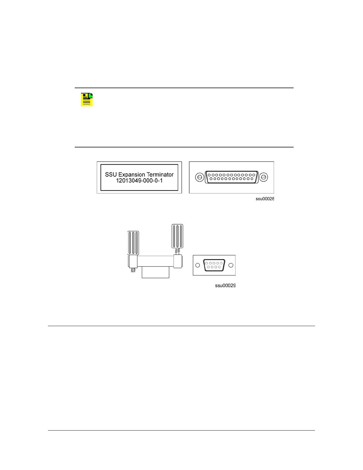
1. Install the BUS Termination Assembly (12013049-000-0-1, shown in Figure 2-10)
on connector J8 of the main shelf.
2. Install an SDU Backup Clock terminator (551021-0040, shown in Figure 2-11) on
connector J9.
Figure 2-10. SSU Expansion Terminator (J8)
Figure 2-11. SSU Backup Clock Terminator (J9) Side and Front View
Making Alarm Connections
The SSU-2000e Shelf has two filtered DA15P male connectors for local and remote
alarm contact closure connections, as shown in Figure 2-12. The local connections
are made on J1 and the remote connections are made on J2. The connectors are
labeled ALARM CLOSURES, LOCAL (J1) and REMOTE (J2). They each have
connections for normally open (NO), common or wiper (COM), and normally closed
(NC) for each of these alarm categories: CRITICAL, MAJOR and MINOR.
Notes:
If you are not installing expansion shelves, you must install the
Expansion and Backup Clock Terminators on connectors J8 and J9
on the SSU-2000e.
The signals on connectors J8 and J9 are in differential pairs. Each
pair is terminated with a series 1000 pf capacitor (J8) and a 120 Ω
resistor (J9) on external plug-on terminators with locking slide latch.
 Loading...
