12713140-002-2 Revision E – October 2006 SSU-2000e User’s Guide 83
Chapter 2 Installing the SSU-2000e
Installing the SDU-2000e
Installing SDU Modules
The SDU-2000e shelf has 12 plug-in module slots located on the front of the
chassis. The module slots are numbered from left to right looking at the front of the
shelf, A1 through A12. Each module slot has a specific address defined in Table
2-10 below. Each module slot has two hybrid DIN connectors associated with it on
the backplane. The hybrid contacts of these connectors are used for power, logic
ground, and frame ground connections. Each module slot has three pins connected
together on each hybrid DIN connector which are used to detect module removal.
Use the precautions in Handling Modules, on page 73, when handling modules in
the SDU-2000e. Install modules in the SDU-2000e using the procedures in
Installing a Module, on page 75.
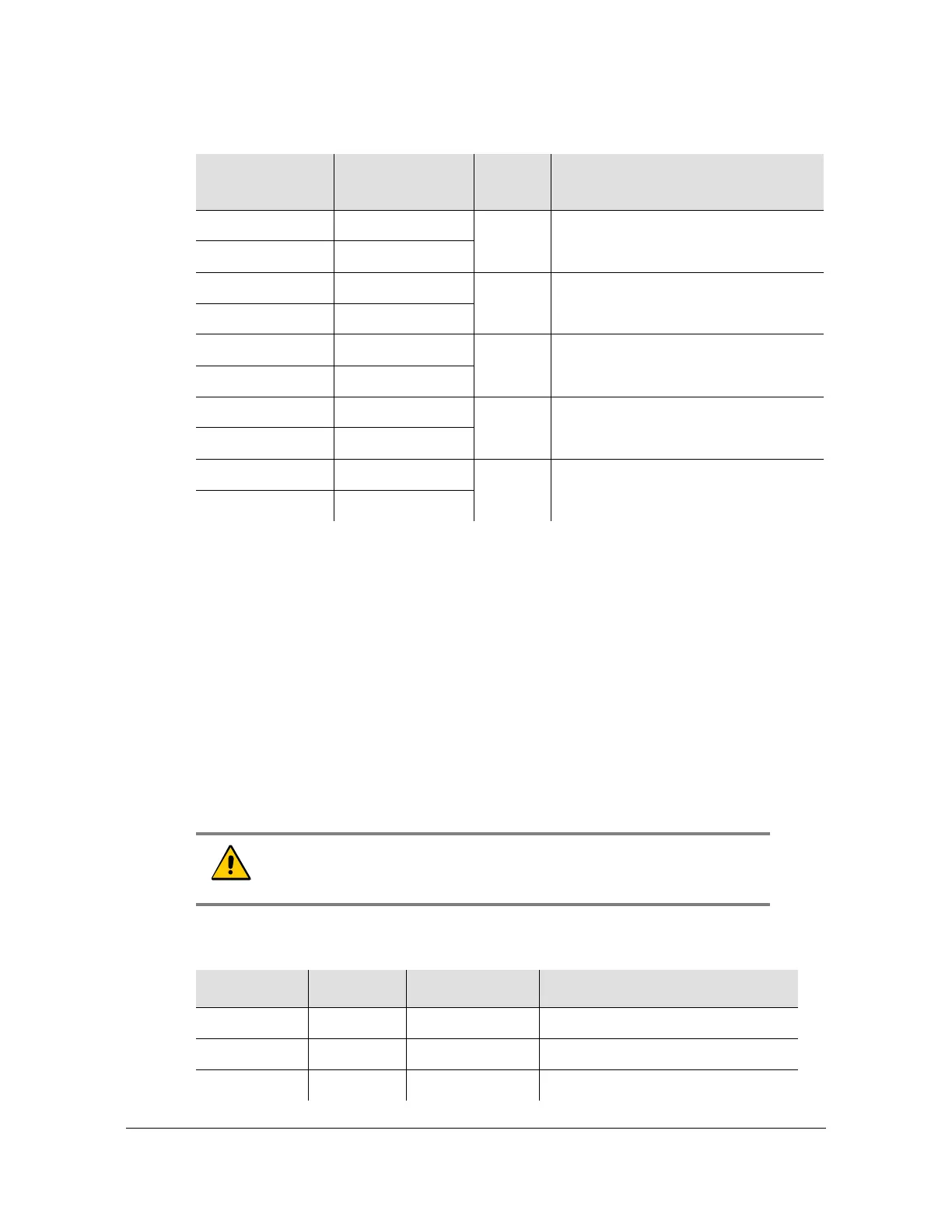
Table 2-9. Output Module Slot to Connector Relationship
Slot Label
(Name)
Plug-in Module
Slot
Group
Output Connector (Module Port)
Reference Description
OUTPUT-1 A1 1 J1 (1) through J20 (20)
OUTPUT-2 A2
OUTPUT-3 A3 2 J21 (1) through J40 (20)
OUTPUT-4 A4
OUTPUT-1 A5 3 J41 (1) through J60 (20)
OUTPUT-2 A6
OUTPUT-3 A7 4 J61 (1) through J80 (20)
OUTPUT-4 A8
OUTPUT-5 A9 5 J81 (1) through J100 (20)
OUTPUT-6 A10
Caution: To avoid damaging the shelf, never insert Output modules
in slots A15 and A16. Insert only Buffer modules into these slots.
Table 2-10. Module Slot Addresses
Slot-A Address Module Types Comments
1, 2 1, 2 Output, Pair 1 Paired Outputs
3, 4 3, 4 Output, Pair 2 Paired Outputs
5, 6 5, 6 Output, Pair 3 Paired Outputs
 Loading...
