2:2 (2), 0-004-7614-0 (GB) TAC AB, 1998-10-23
TAC 2413 Handbook The air handling controller TAC 2413
FF01
ST21
ST22
GT31
GT71
GP71
GT81
P01
SV21
LV01
LK01
P02
SV51
GP61
TF01
GT11
GT21
GT41
SN01
ST41
GX41
GX21
You can choose if you want room or supply air control by using
DIP switch 1. During room control, the control is done from the
sensor GT11, or possibly GT 41, which is chosen with DIP switch
2. The supply air temperature is controlled in cascade via the sen-
sor GT21 which has a minimum and maximum limitation function.
The control signal for the heating coil actuator SV21 is 2–10 V,
but you can set it to 0–10 V by using DIP switch 7. If the heating
coil temperature drops below a set value, SV21 is opened to prov-
ide a minimum limitation. If the temperature keeps dropping in
spite of this, the AHU is stopped and a freezing alarm is tripped. If
the AHU stops, the GT81 sensor helps hold the return temperature.
The control signal for heat recovery (HEX, or VVX in the pictu-
res) is 0–10 V. The efficiency is calculated using the sensors
GT31, GT41 and GT71. An alarm is tripped if it is too low.
During defrosting, the control signal for the VVX is controlled to
an optimum setting, and if the defrosting is not complete, TF is
stopped to quicken the process further. If the defrosting will run
for too long, the AHU stops and an alarm is tripped. The alarm is
reset in the controller.
The control signal to SV51 is 2–10 V, but you may set it to 0–10 V
by using DIP switch 7. The cooling coil actuator is allowed to
control the cooling valve only when the room temperature has
reached the cooling setpoint. Both SV21 and VVX have to be
closed, and the date has to be within the summer period, for this
to apply.
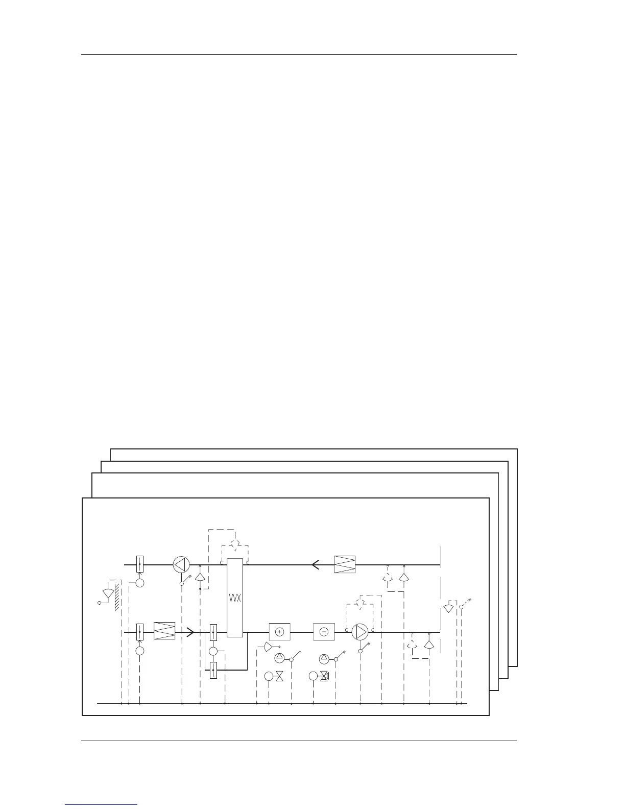
Flow diagram for TAC2413.
Flow diagram with: Plate HEX, SV heating, SV cooling, cooling recovery. Room control.
Flow diagram with: Rot. HEX, SV heating, SV cooling, cooling recovery. Room control.