7:12 (24), 0-004-7614-0 (GB) TAC AB, 1998-10-23
TAC 2413 Handbook Functional description
7.3.9 Heating coil
When the heating demand cannot be met, in spite of the heat recovery
AHU controller being set to maximum recovery, the control sequence
will include the heating coil. The control signal of the heating valve is
2–10 V, but by using DIP switch 7, 0–10 V can be chosen, where
2 (0) V = 0 % is equal to a closed valve and 10 V = 100 % is equal to
an open valve.
The output is controlled either by the supply air controller, a mini-
mum limitation controller or a holding controller.
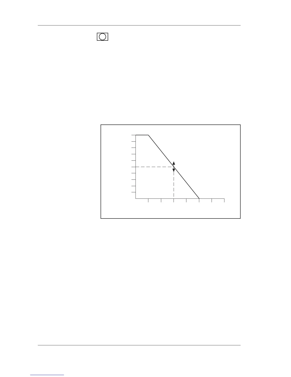
During the start-up sequence of the AHU, the heating valve opens accor-
ding to the outdoor curve, see the figure below. During the transition
from 1/2 to 1/1 speed, the P band of the supply controller is cut in half.
The minimum limitation controller makes sure that the return water
temperature is kept above the set minimum temperature. However,
this particular temperature may never be set lower than 1 °C above the
frost protection temperature.
During the heating sequence, the heating coil is controlled in sequence
with the HEX/mixed air damper. When the heating coil is in danger
of freezing, the frost protection guard in the return duct will force the
valve actuator to open. If there is still a risk of freezing, the AHU is
stopped and an alarm is tripped. When the AHU is stopped, the frost
protection sensor maintains the return water temperature at a constant
level (holding).
The holding controller keeps the return water temperature at an adjus-
table value when the AHU has stopped, regardless of the reason for
the stop. When the supply air fan is started, the supply air controller
takes over.
-30 -20 0-10 10 20 30
10,0
20,0
30,0
40,0
50,0
60,0
70,0
80,0
90,0
100,0
Valve position (%)
Outdoor temperature (°C)
P 34
+