TAC AB, 1998-10-23 0-004-7614-0 (GB), 3:5 (6)
TAC 2413 Handbook Using the operator’s panel
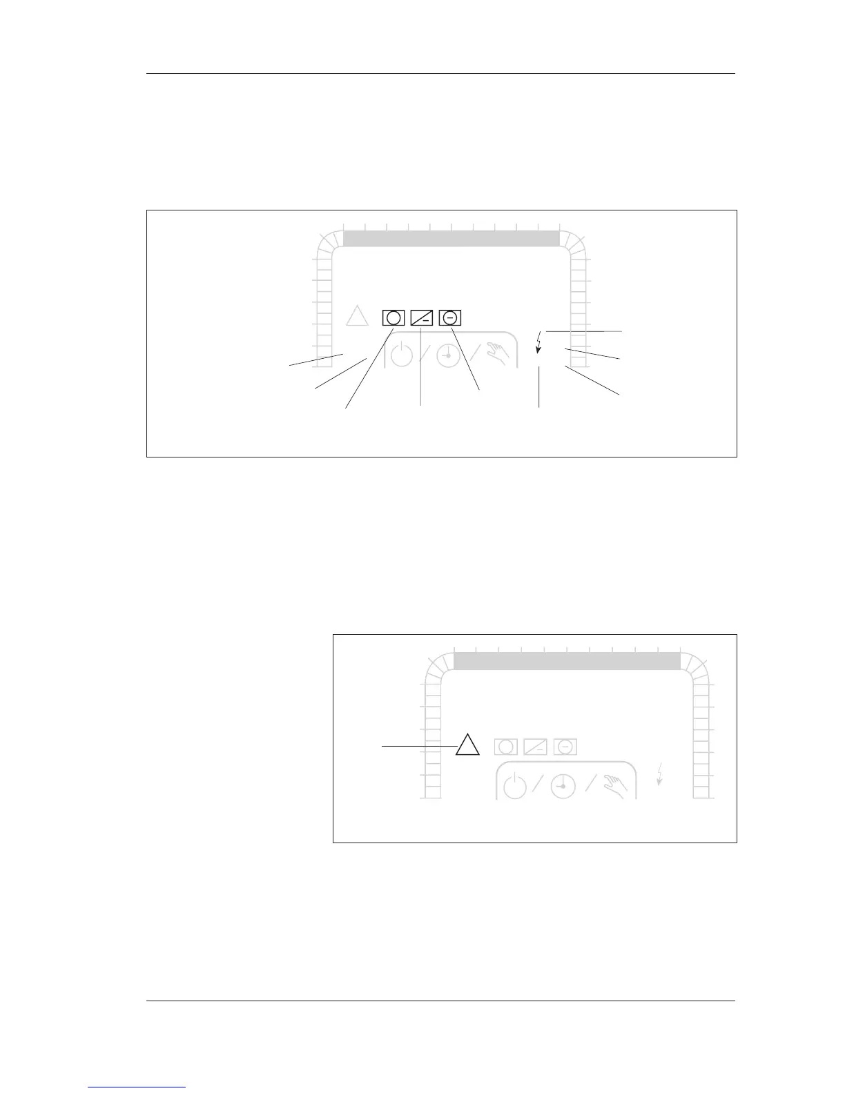
3.2.4 Outputs of the controller
The controller has a number of outputs for control, such as for the
heating coil, and for controlling external units, such as the heating
coil pump. When an output is active, its symbol is shown in the
display window.
The symbols for the outputs of the controller
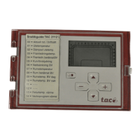
3.2.5 Alarms
When there is an alarm, an alarm symbol will flash in the display
window together with the symbol of the part of the installation
that the alarm is referring to. For example, when the frost protec-
tion guard has been triggered, the alarm symbol and the heating
coil symbol will flash.
The alarm symbol
Chapter 4 describes how to read alarms in the section Reading
alarms. There is further information on the alarms of the control-
ler in the Alarms section in Chapter 7.
1
1
1
2
1
2
3
4
5
6
78910 121314151617
18
0
23
22
21
20
19
24
TF
TU WE TH FR SA
°C
12:00
P 00
MO
11
FF
Dx
Pv
Pk
+
%
SU
!
+
1
2
3
4
5
6
8 9 10 12 13 14 15 16 17
18
0
23
22
21
20
19
24
TF
TU WE TH FR SA
°C
12:00
P 00
MO
11
1
1
1
2
FF
Dx
Pv
Pk
!
+
%
SU
+
7
supply air fan
return air fan cooling coil pump, cooling coil
heating coil heat recovery pump, heating coil
DX cooling
alarm
electric heat