7:16 (24), 0-004-7614-0 (GB) TAC AB, 1998-10-23
TAC 2413 Handbook Functional description
7.3.12 Cooling coil, DX cooling, D
X
DX cooling may be chosen by using DIP switch 6, and the choice is
only valid if room control applies. One step is controlled using K5,
and if there are several steps, they are controlled via Y3. The control
signal is 2–10 V and by using DIP switch 7, 0–10 V can be chosen.
When the control signal is 2(0) V, it equals 0 % (no control signal);
when it is 10 V, it equals 100 % (full control signal).
DX cooling starts only when the following conditions apply:
• the room temperature has increased to the “Cooling setpoint”
• the HEX and heating valve are both closed
• the current date is within the “Summer period” (cooling control).
The heating control takes effect only when the room temperature has
decreased to the “Heating setpoint”.
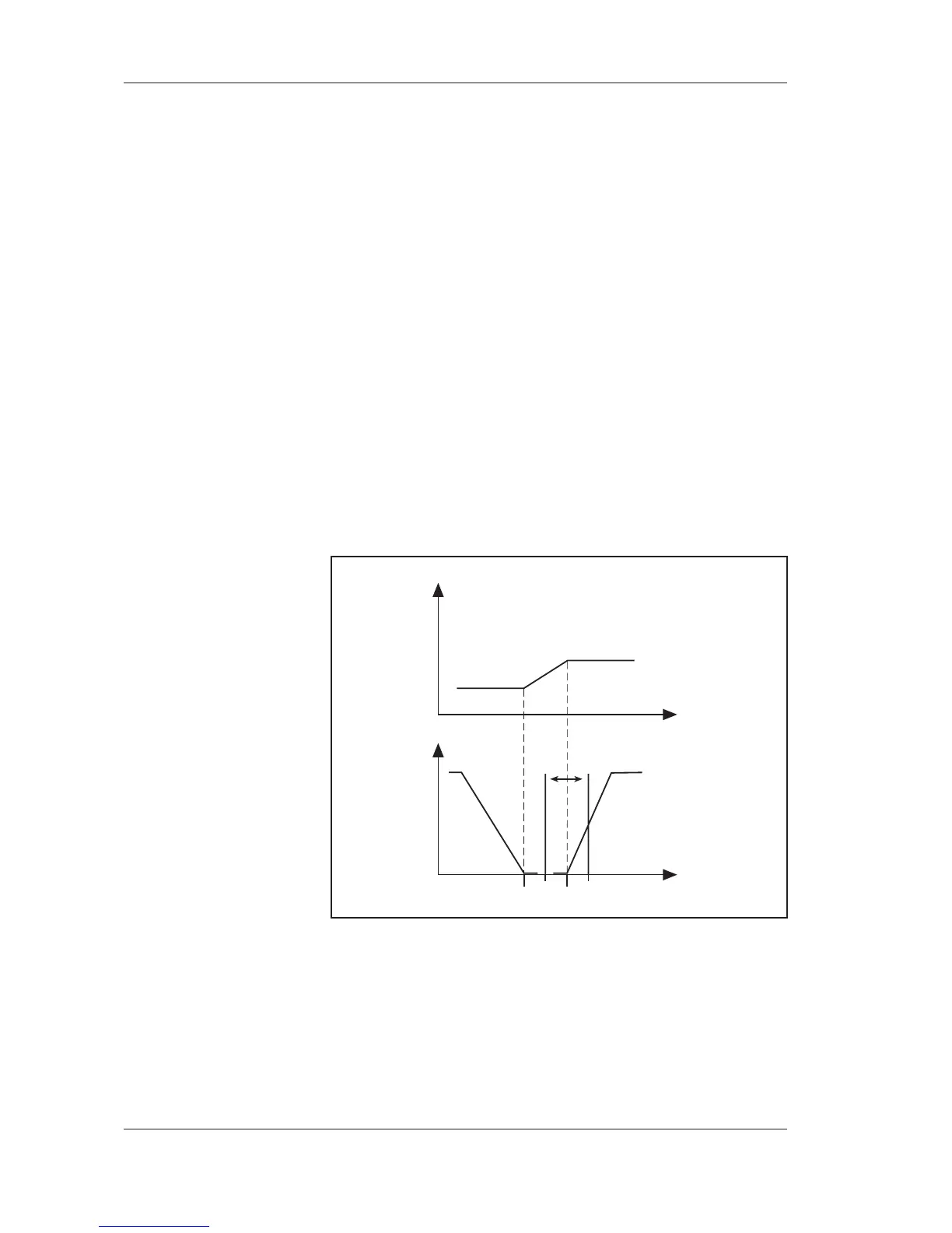
During cooling control, the DX cooling is controlled directly from the
room sensor. The control is done using only the P function. The pro-
portional band is set to the difference between the heating and cooling
setpoints automatically. The control is done above the cooling set-
point, see the figure below.
Example: If the cooling setpoint is 22 °C, and the heating setpoint is
20 °C, then the P band is 2.
The result is that if the room temperature is 22 °C, the output signal
will be 0 %, and if it is 24 °C, the output signal will be 100 %. The
digital output K5 uses “on/off” control with ±1 °C around the cooling
setopint; this means that if the temperature is 23 °C, output K5 is set,
and it is reset at 21 °C.
room temperature
heating setpoint
20 °C
cooling setpoint
22 °C
load
function
heating
neutral zone
DX cooling
off on
K5
load
Y3