7:6 (24), 0-004-7614-0 (GB) TAC AB, 1998-10-23
TAC 2413 Handbook Functional description
P No. Parameter Min Max Factory set. Change Comment
P 02 Supply air temp. setpoint Calculated
P 04 Room/exhaust air temp. SP Calculated
P 10 Heating setpoint 0 °C 50 °C 20 °C
P 11 Cooling setpoint 0 °C 50 °C 22 °C
P 26 Min. SP supply air, heating 0 °C 50 °C 14 °C
P 27 Min. SP supply air, cooling 0 °C 50 °C 12 °C
P 28 Max. setpoint supply air 0 °C 50 °C 35 °C
P 70 Gain, room controller 1 20 2
P 71 I time, room controller 1min 60 min 20 min
P 89 Room sensor adjustment –5 °C 5 °C 0 °C °C/°C
P 92 Dead zone, supply air c. 5 20 5 ×0,1 (5=0,5°C)
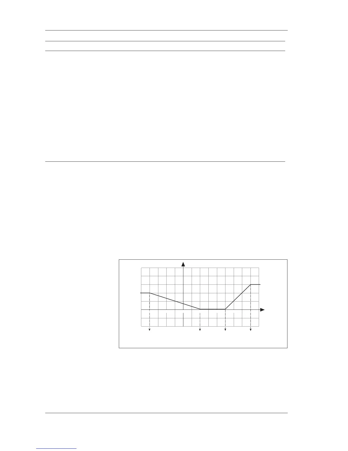
7.3.3 Outdoor compensation
If no outdoor sensor is installed, this function will not be available,
and the P No. is not shown. The supply air or room temperature set-
point can be compensated directly by the outdoor temperature. The
compensation, which may be positive or negative, states in °C how
much the supply air or room/return air temperature setpoint is to be
shifted.
There are two curves, one for the summer and one for the winter com-
pensation, see the figure below.
The outdoor compensation is not active on delivery. It is activated by
setting the desired compensation values in the list, P 50 for winter
compensation and P 53 for summer compensation.
The summer compensation starts when the outdoor temperature is
greater than “Start summer compensation”. The maximum com-
pensation is achieved when the outdoor temperature is greater
than or equal to “Stop summer compensation”.
8
0
–20
–10
10
20 30
40
6
4
2
Max w.comp.
Max s.comp.
Outdoor temp.
(°C)
Start
w.comp.
Start
s.comp.
Stop
s.comp.
Stopp
w.comp.
Compensation °C