TAC AB, 1998-10-23 0-004-7614-0 (GB), 8:1 (2)
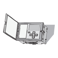
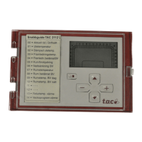
TAC 2413 Handbook Technical data
8 Technical data
Thermistor inputs
Thermistor type ..................................................... 1800 Ω/25 °C
Measurement range:
Supply air temperature, B1 ........ 0 °C – +45 °C
Outdoor temperature, B2 ....... -30 °C – +45 °C
Room temperature, B3 ............... 0 °C – +45 °C
Return sensor, B4 ..................... 0 °C – +120 °C
Maximum deviation
1
:
–30 °C – ±0 °C .......................................... ±1 °C
±0 °C – +30 °C ....................................... ±0,5 °C
+30 °C – +120 °C ...................................... ±1 °C
Relay outputs
Maximum voltage (N.B.! does not apply to K6) ...... 250 V AC
Maximum current (cos φ>0,5) ............................................... 2 A
Inputs
Sensory inputs, B1-B4, U1, U2 ... thermistor inputs, see above
Remote setpoint control (SPC/CO
2
), U3 ..................2–10 V DC
Pump alarm, X3......................................... closing contact on M
Half speed operation (1/2), X1 ................ closing contact on M
Full speed operation (1/1), X2 ................. closing contact on M
Fan alarm, U4 ............................................ closing contact on M
Outputs
Supply air fan (TF), K1..........................relay output, see above
Return air fan (FF), K2 ..........................relay output, see above
Full speed (1/1), K3 ...............................relay output, see above
Pump, heating coil, K4 ..........................relay output, see above
Pump, cooling coil, K5..........................relay output, see above
Sum alarm, K6 ................................................ relay output, 24 V
Heating coil, Y1 (2 mA) ...................0–10 V DC or 2–10 V DC
Heat recovery, Y2 (2 mA) .........................................0–10 V DC
Cooling coil, Y3 (2 mA) ...................0–10 V DC or 2–10 V DC
1
The accuracy of the sensor is not included.