TAC AB, 1998-10-23 0-004-7614-0 (GB), 7:5 (24)
TAC 2413 Handbook Functional description
P No. Parameter Min Max Factory set.Change Comment
P 18 Output signal to HEX (%) 0 100
P 19 Output to heating valve (%) 0 100
P 20 Output to cooling valve (%) 0 100
P 21 Winter/Summer period 0 1 (0/1) Confirms the status
P 22 Night cooling 0 1 (0/1) Confirms the status
P 23 Defrosting 0 1 (0/1) Confirms the status
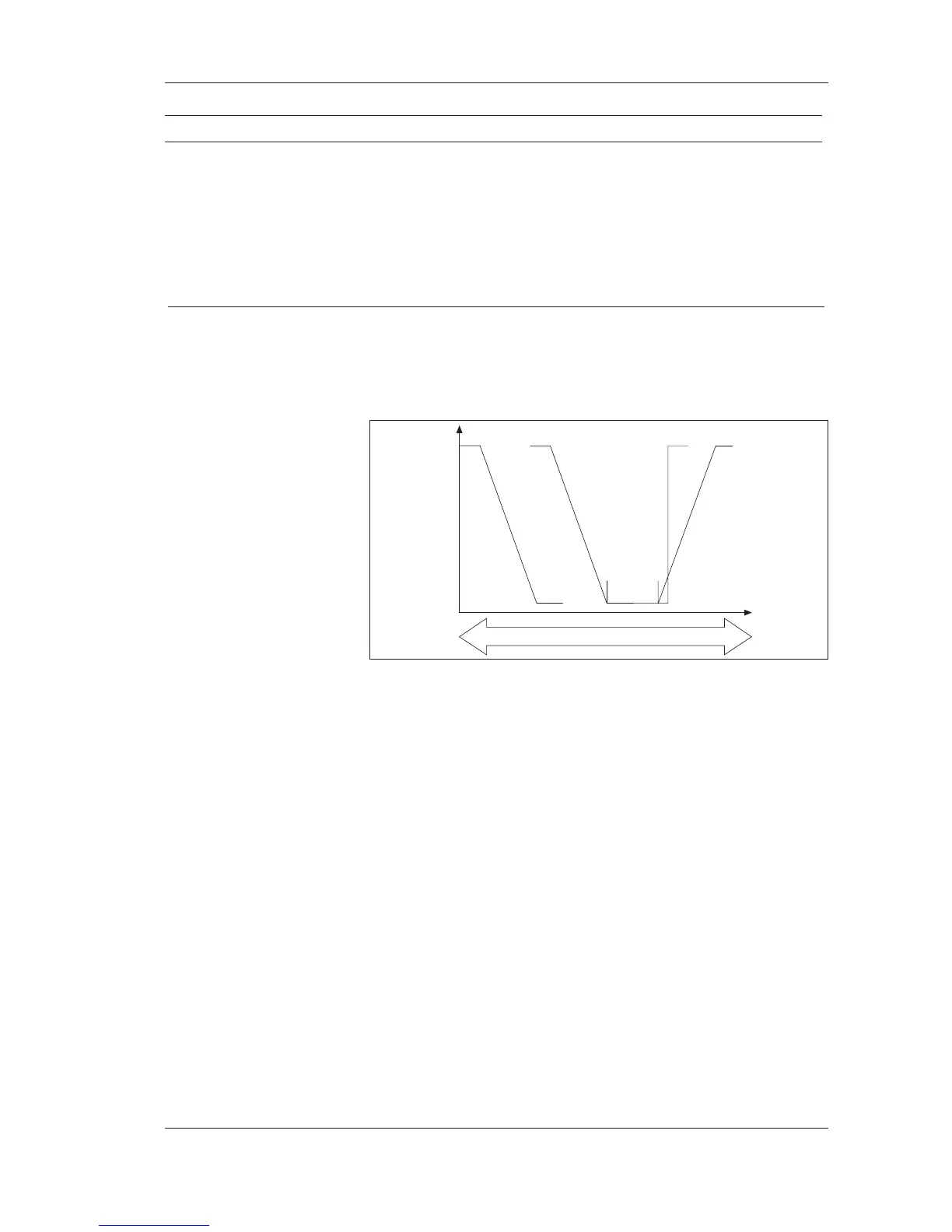
7.3.2 Temperature control
TAC 2413 holds the temperature by sequence control of the heating
coil, heat recovery and cooling coil, see the figure below.
When there is a heating demand, the HEX increases the control signal
to 100 %; then, the heating valve opens. During a cooling demand,
the heating valve closes first, and then the control signal to HEX is
decreased to 0 %. Only at this point does the cooling valve open.
The HEX and heating control have the same setpoint, “Heating set-
point”. The cooling coil uses a separate “Cooling setpoint”. The
“Heating” and “Cooling” setpoints may be adjusted separately and the
difference between them must be at least 0,5 °C.
If the temperature is within the neutral zone, none of the heating coil,
heating recovery or the cooling coil are active. The separate heating
and cooling setpoints mean that heat or cold is only supplied when
there is a real demand, in addition to eliminating the risk of overlap-
ping between the steps.
During normal operation, the room or supply air temperature is con-
trolled. The choice is made using DIP switch 1, which is factory set
to supply air control. During room control, the supply air temperature
is controlled in cascade, and it may also be maximum and minimum
limited. Separate min. limits apply to heating and cooling, respective-
ly. When room control is chosen, further choices may be made if the
control is to be done from the room or return sensor by using DIP
switch 2. The room temperature reading can be adjusted using P 89.
100 %
0 %
heating demand cooling demand
heating coil HEX cooling coil
neutral
zone
cooling recovery