7:4 (24), 0-004-7614-0 (GB) TAC AB, 1998-10-23
TAC 2413 Handbook Functional description
The heat recovery is controlled to 100 % when FF starts, and the posi-
tion of the heating valve is determined by the outdoor temperature. It
is completely closed at outdoor temperatures ≥ 10 °C, and opens on a
linear basis without breakpoints with decreasing outdoor temperatures.
The slope of the curve is defined at –10 °C and is factory set to 50 %. If
no outdoor sensor has been installed, the slope is equal to that at –10 °C.
During electric heating, the same time delay applies between the fans,
but the control signal to the electric battery is 0% until TF starts. The
control sequence is started together with TF.
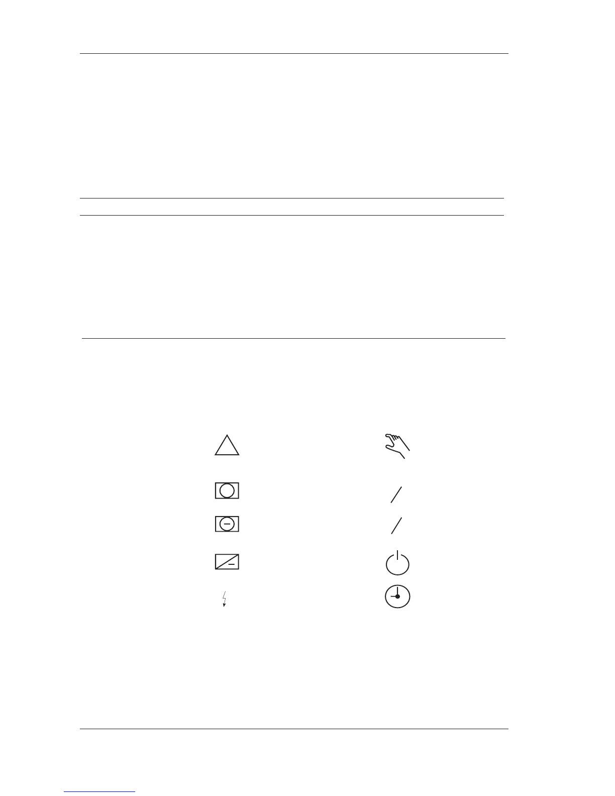
P No. Parameter Min Max Factory set. Change Comment
P 32 Delay, start TF at 5 sec 300 sec 5 sec
+10 °C
P 33 Delay, start TF at 5 sec 300 sec 60 sec
–10 °C
P 12 Weekly program 1/2 speed 07-17 Mon-Fri, one speed op.
P 13 Weekly program 1/1 speed
P 14 Timer 0 min 300 min 120 min Extended operation
P 90 Outd. temp. block 1/1 speed –50°C 20°C –50°C
Status
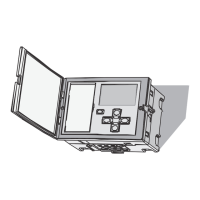
The display shows the functions that are activated using the P No.
When an output signal is active for the AHU, its symbol is dis-
played. The following symbols are found on the display:
!
: Alarm : Manual
operation
+
: Heating coil
1
2
: Half speed, one
sp.
: Cooling coil
1
1
: Full speed
+
: Heat recovery : Off
: Electric heating : Timed operation
FF : Return air fan D
X
: DX cooling
TF : Supply air fan P
K
: Pump, cooling
coil
P
V
: Pump, heating
coil