Interfaces User guide
162
Interface cable (serial
interface)
The cables used must be shielded. The cable shield must be con-
nected to the connector shield on both ends.
It depends on the menu setting whether DTR or RDY is active
at pin 4.
Input signals
Output signals
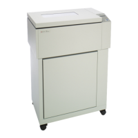
PC/AT (9-pin) Printer (9-pin)
RxD 2 3 TxD
TxD 3 2 RxD
CTS 8 4 DTR/RDY
SG 5 5 SG
DSR 6
DTR 4
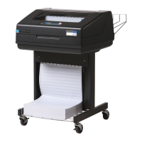
PC/AT (25-pin) Printer (9-pin)
FG 1 FG
TxD 2 2 RxD
RxD 3 3 TxD
CTS 8 4 DTR/RDY
SG 5 5 SG
DSR 6
DTR 4
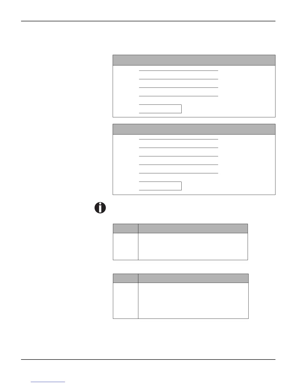
Signal Function
CTS Clear to Send
DSR Data Set Ready
RxD Receive Data
Signal Function
DTR Data Terminal Ready
RTS Request to Send
READY Ready to receive data
TxD Transmit Data