54
MDX 5.1
The MD - 5.1 algorithm occupies:
@ Normal Sample Rate : 1/4 DSP Resource
@ Double Sample Rate : 2/4 DSP Resource
Algorithm Inputs/Outputs are distributed as follows:
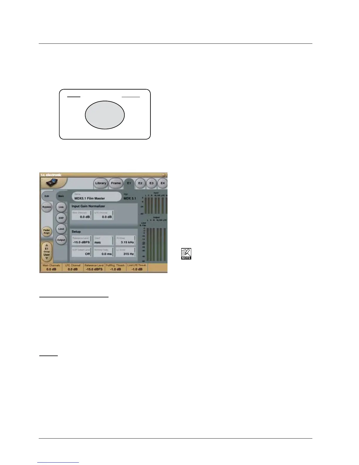
Main
Input Gain Normalizer
Main Channels + LFE
Range:-18dBto+18dB
As we process in a 48 bit domain both positive and
negative gain normalization can be performed prior to low
level processing and output limiting. These gain controls
therefore operate in a safe location, well protected from
generating output overloads.
Setup
Reference Level
Range:-24dBFSto0dBFSin0.5dBsteps
This parameter sets the reference level in the algorithm.
The reference level is the level at which the Threshold
parameters will start operating when set to 0dB.
E.g.iftheReferenceLevelissetto-18dBFS(often
referred to as 0dBu), a Threshold setting at -4dB, will
causetheCompressortostartoperatingat-22dBFS.
DXP Defeat Level
Range: Off to -3dB
MDX5.1mayremovelowlevelgainbelowthethresholdset
with this parameter to avoid having irrelevant sources (e.g.
backgroundnoise)becomeaudible.Lowlevelgainisnot
revokediftheDXPDefeatLevelparameterissettoOff.
The Defeat threshold is relative to DXP Band Thresholds,
which are relative to Reference Level.
Example: If Reference Level is set at -20 dBFS, Band
Thresholds at -15 dB, and DXP Defeat at -22 dB, low level
boost starts rolling off at -47 dBFS. See example at page 18.
Crest
Range:Peak,6dB,10dB,12dB,14dB,16dB,20dB,24dB,RMS
SelectcompressionmethodbetweenRMSandPEAK.
ThedBstepsbetweenRMSandPeakarethedBsneeded
forapeak-valuetooverrideRMSmeasurement.
Nominal Delay
Range:0to15ms
(<2msin0.1mssteps.>2msin0.5mssteps)
Sets the nominal Delay of the signal compared to the
Sidechainsignal.Thisisalsoknownas“Lookahead
Delay”, enabling the Compressor section to become more
responsive to the incoming signal.
Lo Xover
Range:Offto16kHz
Sets the Cross-over frequency between the Lo- and the
Mid-ExpanderandCompressorbandsforthefivemain
channels(LFr,RFr,Cnt,LSr,RSr).
The two Cross-over points are not allowed to cross
each other. Therefore the parameter range can be
lessthan16kHziftheHiXoverparameterisset
below16kHz.
Hi Xover
Range:Offto16kHz
Sets the Cross-over frequency between the Mid- and the
Hi-ExpanderandCompressorbandsforthefivemain
channels(LFr,RFr,Cnt,LSr,RSr).
E1 - E4
L
R
C
LFE
SL
SR
Xt
L
R
C
LFE
SL
SR
INPUT
OUTPUT
•
•
•
•
•
•
•
•
•
•
•
•
•
•
•
•
 Loading...