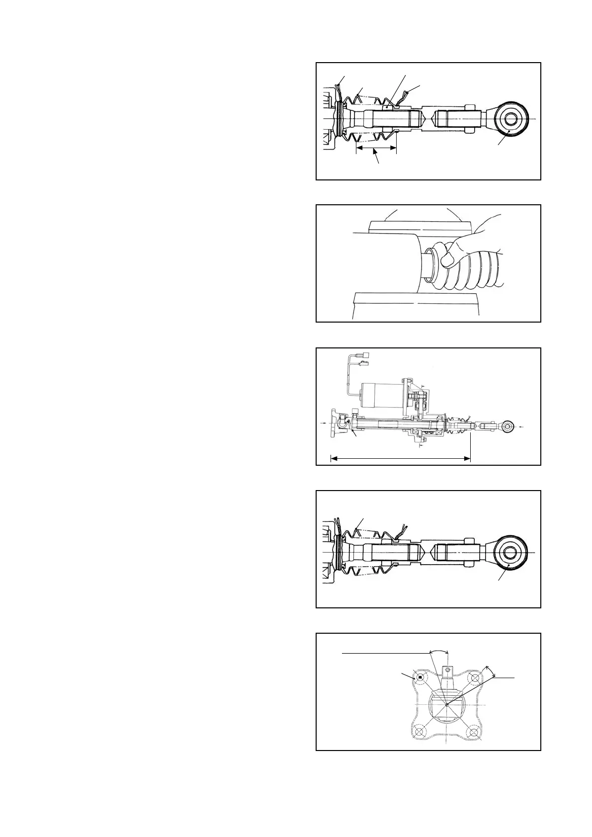
② Remove the clamp of the boot connector
side. Shift the position of the boot. Then
loosen the connector lock nut, and remove
the connector.
Note: Fix the ball joint to prevent it from
turning.
③ Replace the boot with a new one. When
installing the new one, let its end of larger
outer diameter face the actuator.
④ Turn counterclockwise the ball screw till it
contracts the most.
Apply LOCTITE#271 to the threaded areas
of the connector and the lock nut, then install
the connector as specied in Figure 6B.19.
Tightening torque: 176.5 to 215.8 N-m
{18 to 22 kgf-m}
[130 to 159 lbf-ft]
⑤ Clamp the both ends of the boot by wire.
Before clamping, align the position of the
joint, as shown in Figure 6B.21, to correct a
dislocation of the boot.
Fig. 6B.18
Fig. 6B.20
BOOT
BALL JOINT
Fig. 6B.17
BOOT
BALL JOINT
Shift to this position
LOCK NUT
CLAMP
CLAMP
Fig. 6B.19
Push it against actuator.
512 ± 2 mm [20.16 ± 0.078 in.]
Fig. 6B.21
Breather plug direction
(1 to 2.5 t)
MASTER HOLE
20°
(3.0 to
3.5 t)
20°
6B. STEERING SYSTEM (EPS type)



 To Next Page