1.3 POWER STEERING SYSTEM
Circuit Diagram Description
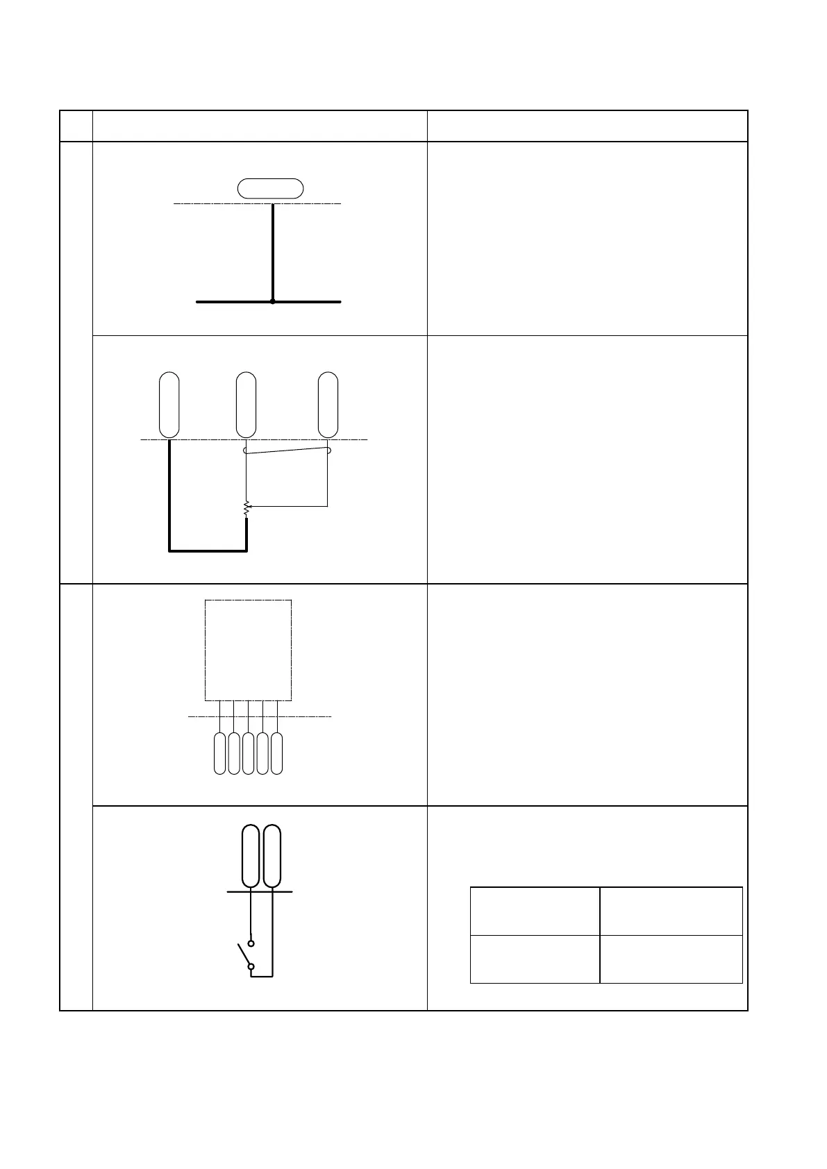
Power Steering System (EPS type)
1. PS motor controller CN1E-17 terminal
When the key switch is turned on, the battery
voltage is present at this terminal and the PS
motor controller is energized.
PSコントローラ
トルクセンサ
(ポテンショメータ)
CN1E-6
CN1E-22
CN1E-23
-
+
G 161
W 162
L 160
2. PS torque sensor
(1) Power supply
4.6 V is supplied from the CN1E-6 terminal.
(2) Input voltage
(a) The EPS motor duty factor is controlled
according to the torque sensor CN1E-23
terminal voltage.
(b) The voltage between CN1E-23 and
CN1E-22 terminals:
In straight-ahead driving: 2.3 V
The voltage decreases when the steering
wheel is turned counterclockwise and
increases when it is turned clockwise.
Power Steering System (Orbitrol type)
SS1
SS2
SSC
ESS
1G
B
Z
+15V
A
GND
LY 249
LG 246
BG 243
BR 230
BY 244
CN2P-25
CN2P-2
CN2P-1
CN2P-13
CN2P-14
1. Steering wheel sensor
(1) The steering wheel sensor detects the
number of rotations and the rotating
direction of the steering wheel.
(2) A pulse voltage develops between CN2P-1
and CN2P-25, and between CN2P-13 and
CN2P-25 according to the rotation of the
steering wheel.
2. EPS/HPS switching terminal
The HPS and EPS units are switched over
by connecting or disconnecting the CN2P-21
and CN2P-29.
When CN2P-21
is connected with
CN2P-29:
HPS (Orbitrol type power
sttering) is available.
When CN2P-21 is
not connected with
CN2P-29:
EPS (electric power
steering) is available.
PS motor controller
Torque sensor
(Potentiometer)
PS motor controller
Pump motor inverter unit
Pump motor
inverter unit
Handle encoder