- 27 -
2. ELECTRICAL PARTS AND PROCEDURES FOR CHECKING
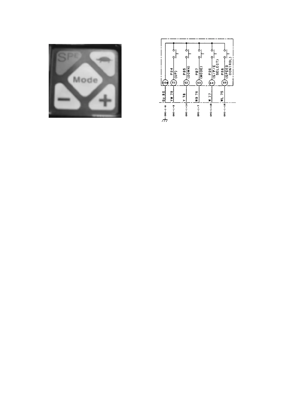
2.2.14 CONTROL SWITCH PANEL
Checking procedure
(1) Checking the truck speed control switch (“turtle” button)
Measure the voltage between the CN9-1-16 terminal (WL) and the CN9-1-8 terminal (Gy) on
•
the LCD panel.
The voltage reading must be as follows: 0 V when the turtle button is pressed and 5 V when the
button is not pressed.
(2) Checking the S.P.E switch
Measure the voltage between the CN9-1-15 terminal (W) and the CN9-1-8 terminal (Gy) on the
•
LCD panel.
The voltage reading must be as follows: 0 V when the S.P.E button is pressed and 5 V when the
button is not pressed.
(3) Checking the “Mode” button
Measure the voltage between the CN9-1-7 terminal (WG) and the CN9-1-8 terminal (Gy) on the
•
LCD panel.
The voltage reading must be as follows: 0 V when the Mode button is pressed and 5 V when the
button is not pressed.
(4) Checking the “-” button
Measure the voltage between the CN9-1-14 terminal (Y) and the CN9-1-8 terminal (Gy) on the
•
LCD panel.
The voltage reading must be as follows: 0 V when the “-” button is pressed and 5 V when the
button is not pressed.
(5) Checking the “+” button
Measure the voltage between the CN9-1-6 terminal (YW) and the CN9-1-8 terminal (Gy) on the
•
LCD panel.
The voltage reading must be as follows: 0 V when the “+” button is pressed and 5 V when the
button is not pressed.