- 28 -
2. ELECTRICAL PARTS AND PROCEDURES FOR CHECKING
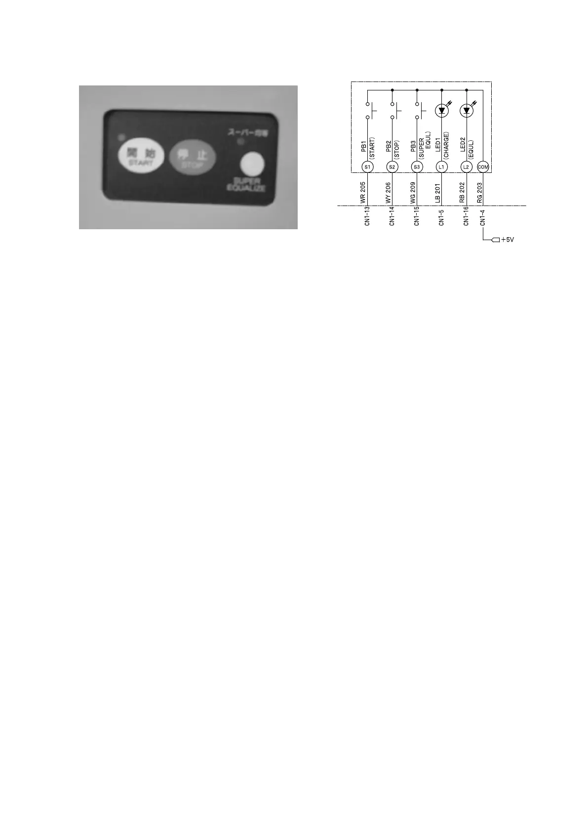
2.2.15 BATTERY CHARGER SWITCH PANEL
Checking procedure
(1) Checking the power supply
Measure the voltage between the CN1-4 (RG) and the CN9-1-5 (BR) on the LCD panel.
•
The voltage reading should be 5 V.
(2) Checking the start button
Measure the voltage between the CN1-13 (WR) and the CN9-1-5 (BR) on the LCD panel.
•
The voltage should be as follows: 5 V when the start button is pressed and 0 V when the start
button is released.
(3) Checking the stop button
Measure the voltage between the CN1-14 (WY) and the CN9-1-5 (BR) on the LCD panel.
•
The voltage should be as follows: 5 V when the stop button is pressed and 0 V when the stop
button is released.
(4) Checking SUPER EQUL button
Measure the voltage between the CN1-15 (WG) and the CN9-1-5 (BR) on the LCD panel.
•
The voltage should be as follows: 5 V when the SUPER EQUL button is pressed and 0 V when
the SUPER EQUL button is released.