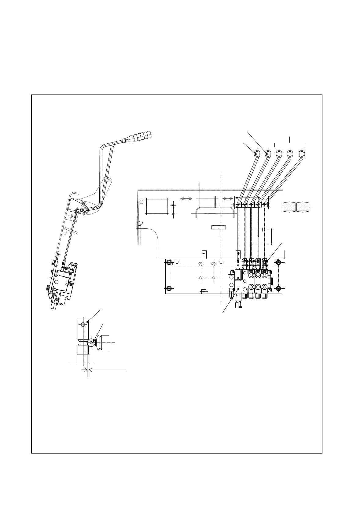
7.1.3 VALVE CONTROL
The control valve plungers are operated with the levers shown in Figure 7.3, with each of the
levers installed on a single shaft.
The bracket supporting each shaft is attached to the cowl. The movement of each lever is
transmitted through the rod to the corresponding plunger.
Fig. 7.3 Valve control
○ Installing the valve switch
Install the valve switch so that it turns on when the plunger is pushed in 0.8 ±0.1 mm
[0.031 ±0.0039 in.].
At this time, the center of switch’s plunger is aligned with the center of the cam.
VALVE SWITCH
PLUNGER
0.8±0.1 mm
(0.031±0.0039 in.)
TILT LEVER
LIFT LEVER
ATTACHMENT LEVERS
(OPTIONAL)
VALVE SWITCH
CONTROL VALVE