1.2 LOAD HANDLING SYSTEM
Circuit Diagram Description
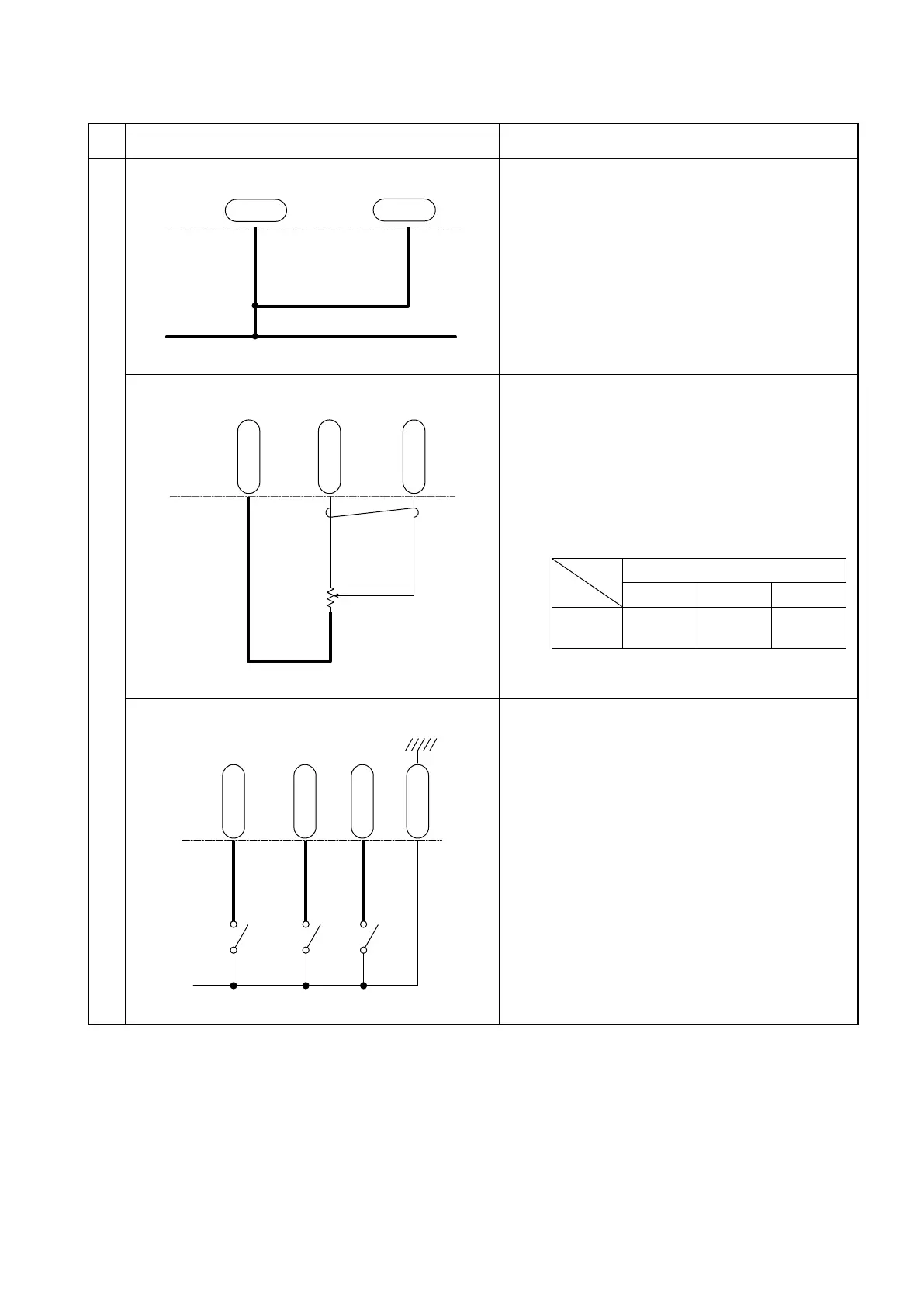
Load Handling System
1. Pump motor inverter unit CN1P-7 and
CN1P-8 terminals
When the key switch is turned on, the battery
voltage is present at these terminals and the
inverter unit is energized.
荷役コントローラ
CN2P-20
CN2P-32
CN2P-8
-
+
YL 94
GR 189
WR 188
2. Lift potentiometer
(1) Potentiometer power supply
4.8 V is supplied from the CN2P-32
terminal.
(2) Potentiometer signal
The voltage between CN2P-8 and
CN2P-20 terminals varies as follows,
according to the amount of lever movement
away from the neutral position.
Lever position
Down Neutral Up
CN2P-8
terminal
1.1 V or
less
1.1 V or
less
2.4 to
4.5 V
荷役コントローラ
CN1P-16
CN1P-17
CN1P-18
CN1P-28
BL 8
YR 20
ATT1
ATT2
TILT
YG 21
YL 22
3. Tilt and ATT1/ATT2 switches
(1) 4.6 V is supplied from CN1P-16,
CN1P-17, and CN1P-18.
(2) When each lever is operated, the switch
turns on to operate the pump motor. (4.6
V→ 0 V)
Pump motor inverter unit
Pump motor inverter unit
Pump motor inverter unit