Circuit Diagram Description
Load Handling System
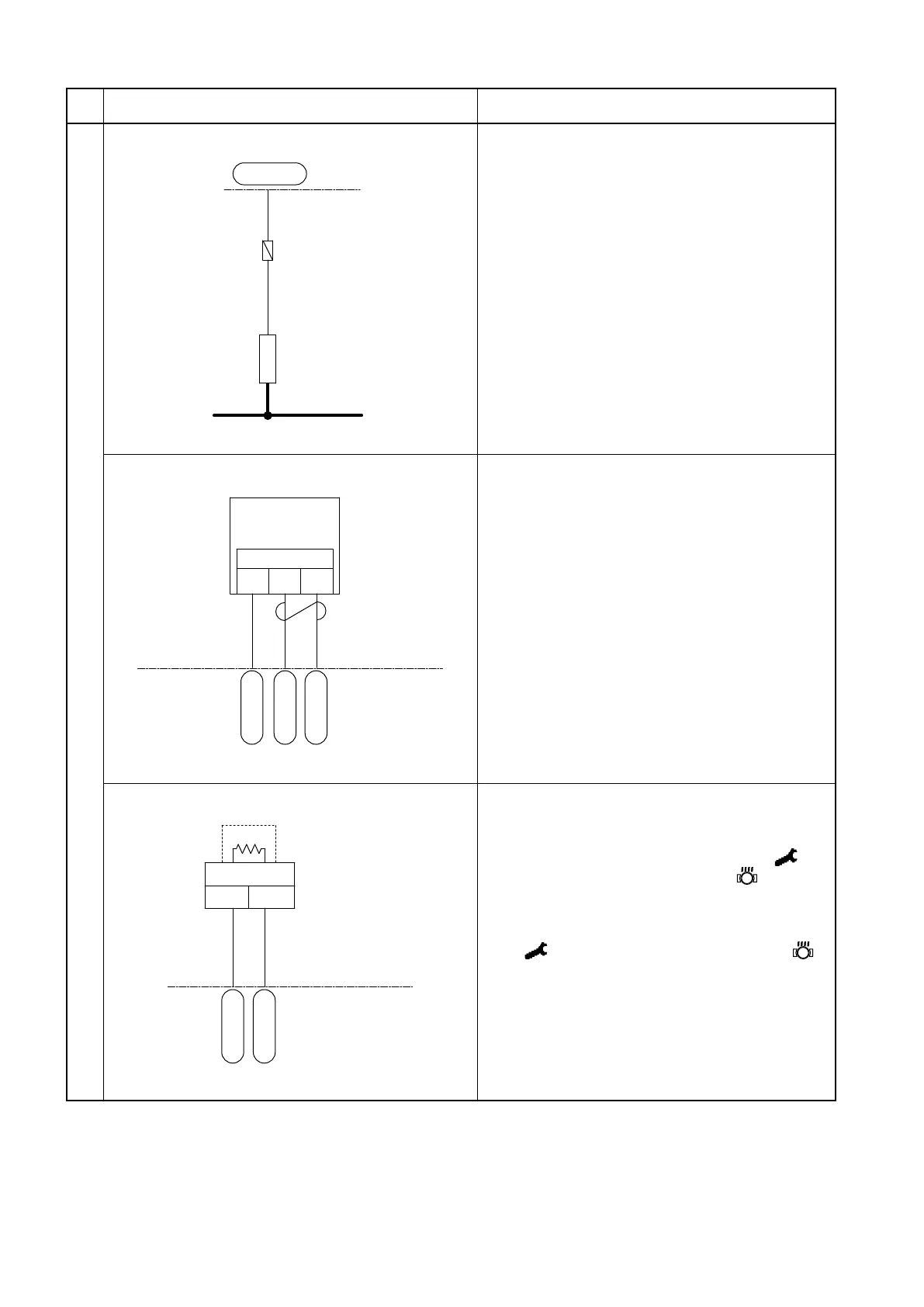
荷役コントローラ
CN1P-35
RL100
LIFT LOCK
SOL
F8
2A
P 139O 138
4 Lift lock solenoid
(1) When the seat switch and the load handling
neutral safety switch are engaged, the lift
lock solenoid is energized.
(2) The voltage between the CN1P-35 terminal
and the negative (-) terminal.
Key switch ON (with seat switch ON): 36 V
Key switch ON (with seat switch OFF): 48 V
荷役コントローラ
CN2P-29
CN2P-5
CN2P-16
2
3
1
(+)
(S) (-)
W 40
B 46
Y 41
荷役モータ回転センサ
5. Pump motor rotation sensor
(1) Detects the pump motor speed.
(2) When the pump motor runs, a pulsed voltage
is generated between CN2P-5 and CN2P-16
terminals.
荷役コントローラ
CN2P-17
CN2P-6
2 1
YW 39
G 38
荷役モータサーモセンサ
6. Pump motor thermosensor
(1) Detects the drive motor temperature.
(2) When the sensor detects a temperature of
145ºC [293ºF] or above, the symbol
406
appears on the LCD panel, the
blinks,
and the motor output is limited.
(3) When the sensor detects a temperature
of 156ºC [312.8 ºF] or above, the symbol
405 appears on the LCD panel, the
blinks, and the motor is stopped.
Pump motor inverter unit
Pump motor rotation sensor
Pump motor thermosensor
Pump motor controller
Pump motor inverter unit
 Loading...
